
Many beginners may have watched some videos or live games, evoked childhood memories, and raised the idea of ​​making robots by themselves. Many people may not be embedded in the industry, or even heard. The term "single-chip microcomputer, stepper motor", looking at other robots running around the ground, quite has nowhere to start feeling. Some people are ready to be a humanoid robot that can walk on both feet, can walk smoothly, can rely on the camera to read environmental information, can be recognized by voice, and can also be deformed...
My opinion is: It is best for novices to start from the car honestly. Humanoid robots can be said to be a systematic project, not a person to play, and the financial investment is not quantifiable. A humanoid robot's molded product must be sold for at least a few thousand pieces - know that you can't make a mistake in the development process. The robot car technology has a lower threshold, less capital investment, and more support for various products and spare parts in the market. Although simple, the functions that can be realized are quite a bit.
I am here to introduce some of the basics of making a robotic car by myself. If you are a master who has done it yourself, then you can go around. I am here to introduce the most basic for the beginners. Theoretical knowledge and some hands-on experience.
So now we start, first of all, the theoretical part - the control structure of the car .
[1] The overall control system of the car
How is the car controlled? Why can the car automatically circumvent after determining the obstacle?
Theory : Control Engineering - A comprehensive engineering technique for dealing with various engineering implementation problems in automatic control systems. It includes the requirements for the automatic control system (ie, the specified indicators), design, construction, operation, analysis, inspection and other processes. It was developed on the basis of electrical engineering and mechanical engineering.
Closed-loop control : Closed-loop control has a feedback link. The feedback system is improved in system accuracy and shortened response time. It is suitable for systems with high response time and high stability requirements.
Open-loop control : There is no feedback link in open-loop control, the stability of the system is not high, the response time is relatively long, and the accuracy is not high. It is used in a simple system that does not require high stability and accuracy of the system.
Generally, the slightly more complicated robot car is closed-loop control, which means that it has a feedback mechanism that reads environmental information according to various sensors that it is equipped with, and decides its next action based on the environmental information. The action command is then sent to the execution system to enable the robot to make the appropriate action. Of course, some robot cars are open-loop control. I have seen a robot car with a pen, put the robot on the paper, the robot turns, brush a circle on the paper, of course, due to friction For reasons such as mechanical errors, the circle drawn may not be closed or may not be round. However, everyone Ah Q said: "The circle that Grandson painted..."

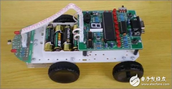
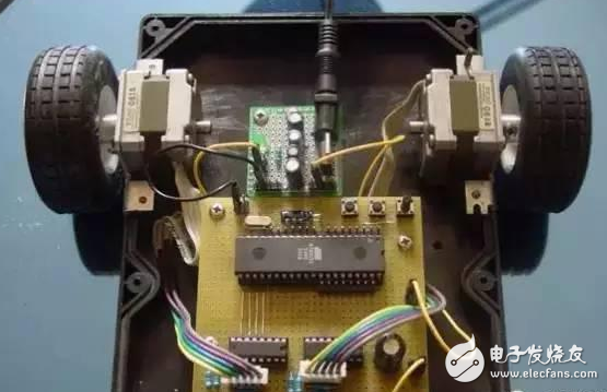
A little confused? It doesn't matter, in fact, it is simple: the robot can be divided into three parts - the sensor part, the controller part, and the actuator part.
Sensor section : A sensor used by the robot to read various external signals, as well as various switches that control the motion of the robot. It is like a person's eyes, ears and other sensory organs.
The controller part : receives the signal transmitted from the sensor part, and determines the reaction of the robot to the external signal according to the decision system (software program) written beforehand, and sends the control signal to the actuator part. Like the human brain.
Actuator section : Drives the robot to perform various actions, including the parts that emit various signals (lighting the LEDs, making sounds), and can adjust their state according to the signals of the controller part. For the robot car, the most basic is the wheel. This part is like the limbs of a person.
Ok, now let's analyze the obstacle avoidance behavior control of the robot car: the robot is walking (the person is walking on the road), and suddenly receives a "left front obstacle" from the sensor mounted on the front of the robot. The signal (the human eye finds a pole in the left front), the program algorithm we wrote in advance in the robot control chip requires the robot to find an obstacle in the left front and turn to the right (people find that there is a pole in the left front and should go to the right - - What, you have to go ahead? You cow! Then I will wait to hear it, oh, you just want to see the small ad above...), control the chip to the robot drive - or the wheel , or two feet - the command to turn right (the human brain sends a command to turn right, the popular point is that "turned a turn"), at this time the robot's actuator part should immediately respond to the controller's instructions, Change your state, change the direction of the robot, avoid obstacles (congratulations, avoid the pole). How do you mean that there is a point machine "person"?
So how do these three parts relate? Very simple: electricity! In fact, the robot car is an electronic work. The sensor converts external optical signals, sound signals, temperature signals, etc. into electrical signals that can be accepted by the control part. The commands issued by the control system are also various electrical signals, which are converted into motor outputs through the execution part. Torque, sound, light signals, and more.
Let me introduce these three parts separately .
[two] sensor part
The sensor is the eye of the robot, and it is necessary to equip the sensor with different sensors for different tasks.
There are so many sensors on the market today that there are many collision detection sensors (collision switches), infrared measurement sensors, infrared distance sensors, photoresistors, electronic thermometers, electronic compasses, etc., which are commonly used by personal robot enthusiasts.
The sensors used by general robots return two kinds of signals: one is simple, and there are only two states: "yes" or "no"; "yes" or "no"; "0" or "1". I am generally used to refer to this amount as the "state quantity." It reflects a state, just a simple "yes" or "no". For example, "There is no obstacle on the left side of the robot", "There is no sound signal" and so on. Another return value returns any value within a known range. For example, a signal returned by a photoresistor may be any voltage signal in the range of 0 to 5V. I generally refer to this amount as the "intensity amount." It reflects the intensity within a valid range. For example, "How far is the obstacle on the left side of the robot?", "How strong is the current sound signal?"
The “status quantity†reflects the simpler information, and the corresponding sensor is simpler and the cost is lower. The amount of information reflected by the “strength amount†is richer, and the cost of the corresponding sensor will be higher, and the control will also bring greater flexibility and complexity.
Let's look at some commonly used sensors:

Collision switch : The circuit is normally open. When it touches an obstacle, it can be connected to detect whether the robot collides.
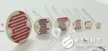
Photoresist : A photoresistor is a resistor made by the photoelectric effect of a semiconductor, which changes with the intensity of the incident light; the incident light intensity, the resistance decreases, the incident light is weak, and the resistance increases. Photoresistors are commonly used for light measurement, light control, and photoelectric conversion (converting changes in light into electrical changes). Can be used to detect light intensity.
Infrared Barrier Sensor : The infrared barrier sensor uses the principle that infrared rays will reflect obstacles to detect the presence of obstacles in a certain direction.
Infrared ranging sensor : The infrared ranging sensor uses the principle that the intensity of different reflections of the infrared signal encountering the obstacle distance is different, and the detection of the obstacle is far and near. The infrared ranging sensor has a pair of infrared signal transmitting and receiving diodes, the transmitting tube emits an infrared signal of a specific frequency, and the receiving tube receives the infrared signal of such frequency.
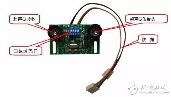
Ultrasonic distance measuring sensor : The ultrasonic distance measuring sensor uses the principle that the transmission distance of sound in the air is proportional to the transmission time, and detects the distance of the obstacle by detecting the difference of the time when the reflection of the different distances is reflected back to the ultrasonic wave.
For sensors, many people think that just look at the documentation and know how to use it. But my advice is: not only to know how to use it, but also to know its detection principle. Only a deep understanding of the detection principle of the sensor can have a better divergent thinking. Let me give you an example: When we started a robot fire fighting competition in school, we used the ground grayscale sensor provided by the manufacturer to rely on visible light reflection to detect the ground white line. The effect has not been ideal. Later, some students carefully studied the photoelectric encoders equipped on the motor at that time, and found that the principle is to use the infrared rays to detect the rotation speed of the motor on the motor with different reflectances in different colors to detect the high-speed rotation of the motor. The infrared detection module on the photoelectric encoder is removed and installed at the bottom of the robot to detect the white line on the ground. The detection effect is much better.
Purchasing route : local electronics market, or online purchase (now many robots have a variety of sensors available, in fact, the principle and scope of application are similar, many can be interchangeable and universal). What you need to pay attention to when purchasing is the voltage range and effective range of the sensor.
Ultimate development : Image recognition relies on a camera to calculate the distance between different objects and their speed according to the video signal returned by the camera. If you can take this step, then the door to a discipline called "machine vision" will open to you.
[three] controller part
There are many control chips for robots: single-chip microcomputers, DSPs, and even CPUs used on our computers. However, we mainly introduce the technology of the robot car here, so put the other ones first, let us put our attention on the inexpensive MCU.
First of all, the theory class, don't complain, my credo is: developers who don't understand theory can only be a assembler.
Single-chip microcomputer : A single-chip microcomputer is also called a single-chip microcontroller. It is not a chip that completes a certain logic function, but integrates a computer system into one chip. In a nutshell: a chip becomes a computer. Its small size, light weight and low price make it easy to learn, apply and develop.
Small chip has great wisdom
The single-chip microcomputer is a widely used control chip in the automatic control system, and now there are many single-chip computers in many of the electrical appliances around us. If you want to make a robot yourself, the corresponding knowledge of the microcontroller is essential. System MCU knowledge I don't want to say more here, I want to have a deep understanding of the MCU system, or find a better MCU textbook to read one page at a time, any "skills" on the Internet "quick start" ( Including this article) can only be regarded as fruit, snacks and the like, can be used to open the stomach when there is nothing to do, really want to eat well, or to eat rice with a big cake roll.
I will only mention some basic entry concepts here, and give the real beginners a little bit of a role to play. A piece of MCU chip that we just got from the merchant is still a blank, and nothing can be done. Like a newly born child, what our developers have to do is to teach the microcontroller to handle a variety of problems, and to equip the microcontroller with a variety of extension tools, so that the microcontroller can simplify and digitize complex problems.
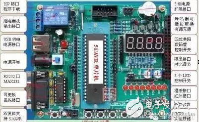
MCU development involves two aspects: hardware and software. The MCU is different from other electrical appliances. It can be used by inserting the latch directly into the power supply. A blank MCU wants to use it, and some other circuits are needed to support it. In general, the most basic circuit is the minimum system of the MCU: the so-called MCU minimum system refers to the most basic circuit that can make the MCU work. In all MCU systems, you can find similar circuits. As for its principle, I will not be tired here, look for the book.
I will introduce some extension circuits that are needed for robots:
Program download circuit: The microcontroller needs the program to control. Generally, the program is written on the PC and downloaded to the MCU through the download line. The download requires a circuit to support. The previous common practice was to connect to the serial port of the PC, but there are now many circuits for downloading programs via USB.
The above two circuits are the most basic single-chip circuits required for robot development. Others may require some circuits such as motor drive, A/D conversion, and switch selection.
Maybe you are a little confused, you can feel a little tricky. These circuits may be a big head for a newcomer who has never touched a single-chip microcomputer. It doesn't matter. There are many mature MCU development systems on the market, and the price is extremely low. If you don't want to If you spend more energy on the underlying circuit, go to some e-commerce websites and search for the "MCU development board". You can buy a full-featured development board with more than one hundred functions, free software + tutorials and technical support services. If you do it yourself, the cost will be lower).
Software : To put it bluntly, it is your own intelligent program developed for the microcontroller, so that the robot can have the simplest intelligence. Don't see how deep the word "smart" is. Seeing that there is a pole in front of you knows that you want to turn, this is intelligence. Different MCUs require different development environments. This is to be clear at the time of purchase. Many MCUs have their own development software, many of which can be downloaded free of charge on the company website. In general, many foreign chip companies have very rich and applicable materials on their own websites. Take the English-Chinese dictionary and browse the information on the website. You will find that everything is very simple.
When I talked about MCU development, I remembered the assembly language. At that time, the cost of the chip was very high. The computational overhead and storage overhead of the chip should be carefully calculated. The high-efficiency assembly language is the best choice for the MCU. Now, with the reduction of chip cost, the overhead problem is no longer a bottleneck restricting the development of single-chip programs. Therefore, many C or Basic language development environments have emerged. As long as you have a certain program development foundation and are familiar enough with the various pins of the microcontroller, it is easy to write a simple intelligent program.
Purchase route : electronic market or online shopping. Now the price of the MCU is very low, and there is no need to consider too much on the price. The key is to choose a suitable one, more information, and easy to get started. As far as robot development is concerned, the following conditions must be met: a program download line can be used to easily download the program from the PC to the microcontroller; integrated A/D conversion; PWM output (for easy control of the motor).
Ultimate development : The ability of single-chip microcomputers is limited. If you want to do some applications with large computational complexity (such as audio and video processing), you need some higher-end chips, such as DSP, or simply add a few of your computer chassis. Wheels, let your computer run!
Related terms: C51, PIC, AVR, PWM ... What do you mean? Search for yourself!
[four] actuator part
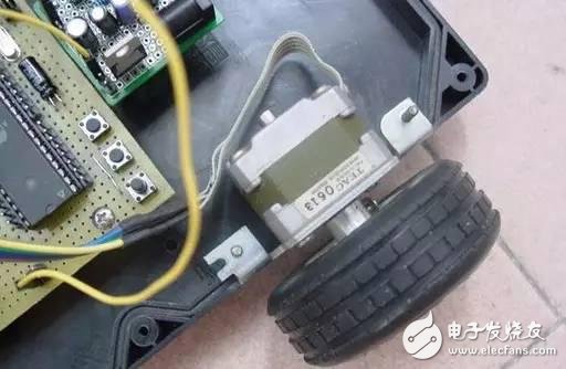
For robotic cars, the most basic part of the actuator is the wheel. To have wheels, the car can be called a car. This part may also be the most worrying part of the fans, sensors and controllers are sold everywhere, and generally suitable for the wheels used in the robot car, mechanical structure, body and other parts are difficult to find. The cost of finding someone is very high, and many of my friends now use toy cars to make modifications. In fact, robotic chassis has been sold now, but it is difficult to see in the electronic market. Most of them must be mail-ordered in online shopping robots.
There are three types of motors commonly used in robots: ordinary DC motors, stepper motors, and servo motors.
DC motor: A rotating motor that outputs or inputs DC power, called a DC motor. It is a motor that converts DC power and mechanical energy. When it is used as a motor, it is a DC motor that converts electrical energy into mechanical energy; when the generator is running, it is a DC generator that converts mechanical energy into electrical energy.
Stepper motor: A stepper motor is an open-loop control element that converts an electrical pulse signal into an angular displacement or line displacement. In the case of non-overloading, the speed and stop position of the motor depend only on the frequency of the pulse signal and the number of pulses, and are not affected by the load change, that is, a pulse signal is applied to the motor, and the motor rotates through a step angle. The existence of this line relationship, coupled with the stepper motor only periodic error without cumulative error. It is very simple to control the change with a stepping motor in the control field such as speed and position.
Servo motor: A servo motor, also known as an actuator motor, is used as an actuator in an automatic control system to convert an received electrical signal into an angular displacement or angular velocity output on a motor shaft. Divided into two major categories of DC and AC servo motor, its main feature is that when the signal voltage is zero, there is no rotation phenomenon, and the rotation speed decreases uniformly with the increase of torque.
Generally speaking, the cost of these three motors is DC <step < servo, and the control precision is DC <step < servo (of course, when there is unusual, it is not that the servo motor is necessarily cheaper than the stepper motor). Beginners are not familiar with the single-chip control motor. You can use the PWM signal output from the single-chip microcomputer to control the DC motor. You can try to control the stepper motor for higher control accuracy. For the motion drive of the trolley, a DC motor or a stepping motor can be generally used, and the servo motor is generally used on the robot arm to obtain a precise rotation angle.
Generally, the single-chip microcomputer must control the stepping motor and the servo motor through the driving circuit. There are special modules to drive the motor. The microcontroller only needs to provide a certain frequency of pulse and control signal for such a module. There are a lot of relevant information on the Internet. If you need it, you can find it yourself.
Purchase path: electronic market, hardware store, online shopping, old appliances.
Ultimate development: When you can control the robot arm freely, you will find that a humanoid robot will not be far away.
Other commonly used drive devices are robotic arm robots, etc., which are mounted on the trolley to grab things. You can use servo motor development (the best for beginners), or you can choose the molded products on the market. These products generally have complete documentation, which is easy to read and use.
[postscript]
Finally, I will introduce some things about electronic circuit development. When I mention the circuit, many of my friends may think of the dark green printed circuit board. Now many people in the electronics market can process printed circuit boards for you according to your circuit diagram. However, in the design stage, many things will be changed. Every time you re-create the board efficiency and cost are big problems. Generally, in circuit development, there is a special experiment board (also called bread board), suitable for Used during the development phase. The above is a little bit of experience I wrote. I didn’t write any specific techniques. I just listed some problems that the novice might be confused. As I said before, this small article can only be regarded as a little snack. Really If you want to be a robot master, you still need to bury some professional books. There are no shortcuts to learning. If you take shortcuts, it only means that you are less than others.
The purpose of this article is just to let some friends who are interested in robots and don't know how to proceed know what they need to make a robot, what kind of knowledge is needed, and they don't want everyone's eyes. I just hope that more friends can join the robot development. Of course, our works will basically have no scientific and technological value, and will not fill any technical gaps. It will not add anything to the socialist construction. It is purely self-entertainment. But I think that when more people, especially students, make robots as an entertainment project, it should be a happy thing, huh, huh.
Solar LED land lamp uses sunlight as the energy source, charges during the day and uses at night, does not need complex and expensive pipeline laying, can arbitrarily adjust the layout of lamps and lanterns, safe and energy-saving, pollution-free, stable and reliable without manual operation, saving electricity and maintenance. Solar LED street lamp is mainly composed of solar cell module (including bracket), LED lamp holder, control box (with controller, battery) and lamp pole.
Solar Led Street Light,Street Light Lamp,Solar Powered Street Lights,Solar Powered Led Street Lights
Yangzhou Heli Photoelectric Co., Ltd. , https://www.heli-eee.com