
1 Introduction
This article refers to the address: http://
Mobile phones have become an indispensable communication tool in people's lives. At present, mobile phones are powered by rechargeable lithium-ion batteries. In the wild or without mains, the mobile phone may be out of power at any time, which brings a lot of inconvenience to the user. After researching that there is always a temperature difference between the human body and the environment, the use of thermoelectric technology can realize the true power of the mobile phone. Thermoelectric technology is a green energy-saving technology. It is a new energy replacement method that can effectively convert the heat of low-grade heat sources into electrical energy, while reducing energy consumption and alleviating environmental pollution problems. Therefore, the miniature thermoelectric device will have a good application prospect, and the mobile phone body temperature charging system must have important practical significance for the development of new energy.
2 The principle of body temperature charging
2.1 The energy of the human body
Under normal circumstances, the infrared wavelength emitted by the human body is 8 ~ 12μm, and the heat energy generated by the human body under basal metabolism is 8 059.8 kJ. The surface area of ​​an adult's skin is about 2 m2 after being unfolded. The surface area is a measure of the average heat generated by energy metabolism within 1 h of approximately 167.9 kJ/(m2·h). The main heat-dissipating part of the human body is the skin. When the ambient temperature is lower than the body temperature, about 70% of the body heat is consumed by the radiation, conduction and convection heat of the skin. The skin temperature at the end of the limbs is the lowest, the closer to the trunk and head, the higher the skin temperature. In cold environments, as the temperature drops, the skin temperature of the hands and feet decreases most significantly, but the temperature of the head skin changes relatively little. It can be seen that the skin temperature of the head is the highest and it varies relatively little with the ambient temperature. Therefore, the body temperature charging system of the mobile phone is suitable for being installed inside the cap, which can improve the charging efficiency.
The mobile phone's lithium-ion battery can be reused by charging or adding energy, and its rated voltage capacity is generally 3.6 V (also 3.7 V). For example, the average working voltage of a lithium-ion battery of AA800 mAh is 3.6 V, the energy is 2.88 Wh, and the heat radiated per unit area of ​​human skin per unit time is about 32.65 W/m2, which is known by energy conversion. The energy radiated for 1 m2 of human skin is about 32.65 Wh. If the lithium ion battery is charged at a charging rate of 0.2 C (160 mA), it takes 5 h to fill the energy of 2.88 Wh. Lithium-ion batteries have a theoretical energy conversion efficiency of about 1.76%. Telkes developed a thermoelectric generator in 1947 with a power generation efficiency of 5%. Therefore, the conversion efficiency can meet the requirements long ago, and the body temperature of the human body is completely achievable in terms of energy conversion for charging the mobile phone.
2.2 Seebeck effect
Thermoelectric power can directly convert thermal energy into electrical energy. As long as there is a temperature difference, the thermoelectric power generation module can generate voltage. There is often a temperature difference between the human body and the ambient temperature, which can be converted into electrical energy to charge the mobile phone using thermoelectric technology. The study found that the two semiconductors are combined and one end is in a high temperature state (heat source), while the other end is open and in a low temperature state (cold source), an open circuit voltage ΔU is generated at the cold source end, which is called a thermoelectromotive force. Known as the Seebeck electromotive force, the Seebeck voltage ΔU is proportional to the temperature difference ΔT between the hot and cold ends:
â–³U=sâ–³T=s(tH-tL) (1)
In the formula, s is called the Seebeck coefficient, and its unit is V/K or μV/K. The Seebeck coefficient is determined by the electronic band structure of the material itself.
3 mobile phone body temperature charging system
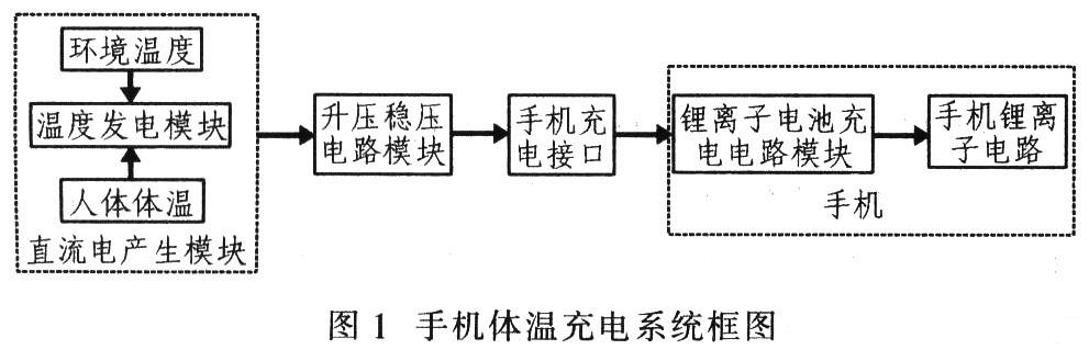
As shown in Figure 1, the mobile phone body temperature charging system mainly includes three parts: a DC power generation module, a boost voltage regulator circuit module, and a mobile phone charging interface. The DC power generation module mainly uses the semiconductor temperature difference battery pack to generate DC power. As long as there is a temperature difference between the environment and the human skin, the temperature difference generates voltage at both ends of the battery pack. The temperature generated by the semiconductor temperature difference battery pack is small. In order to reduce the number of temperature difference batteries, it is proposed to use a booster circuit to achieve boosting to meet the charging requirements of the mobile phone. Since the ambient temperature is unstable, the temperature difference between the two is difficult to stabilize, and the voltage generated by the semiconductor temperature difference battery pack is difficult to stabilize, and the lithium ion battery charging circuit is not satisfied. Therefore, the voltage must be stabilized. The lithium ion battery charging circuit can be supplied with electrical energy.
3.1 DC power generation module
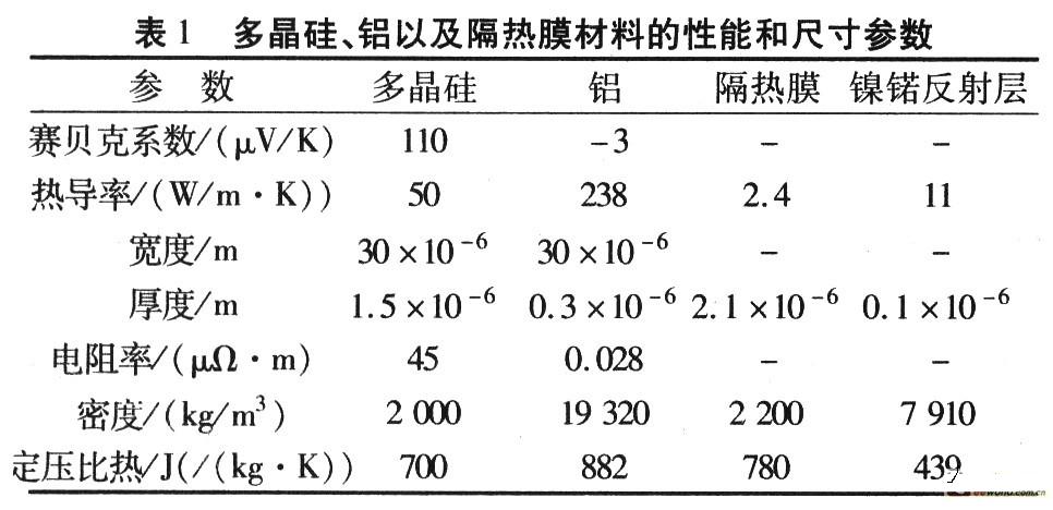
According to the Seebeck effect, a semi-conducting temperature difference battery pack converts thermal energy into electrical energy to generate direct current. The thermoelectric material is a functional material capable of converting thermal energy and electric energy to each other. The parameters are as shown in Table 1. The polysilicon material is selected to produce a thermocouple, which exhibits a high absorption rate of 90% or more with respect to a light source having a wavelength of 10 μm. Considering that the material's figure of merit has an important influence on the power generation efficiency, the semiconductor material has the highest temperature difference coefficient of merit. So it is the material of choice for making temperature difference batteries. The simplest semiconductor thermoelectric power generation unit (Fig. 2) consists of N-type and P-type semiconductor galvanic arms and load resistors RL. It is connected by a metal material (usually copper) and works between a high-temperature heat source and a low-temperature cold source. After the loop, current flows through the load resistor.
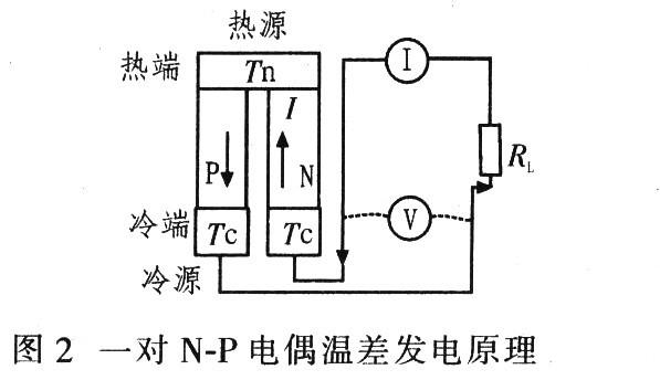
From the viewpoints of ease of manufacture and cost, it is unreasonable that the semiconductor temperature difference battery pack is constituted by a single power generating unit, so that the output power thereof is low. By optimizing the design, several smaller NP galvanic couples are connected in series in the same semiconductor material to form a semiconductor thermoelectric cell (thermoelectric stack) as shown in FIG. In a thermoelectric cell, each galvanic pair operates at the same temperature difference and their function is the same, so the output power of the entire thermoelectric cell is the output power of a single NP galvanic multiplied by the total logarithm, one with N pairs of thermoelectric The thermoelectric voltage U of the even semiconductor temperature difference battery (thermoelectric stack) is
U=Ns(tH-tL) (2)
As can be seen from the structure, the pairs of semiconductor thermocouples are connected in series on the circuit but in parallel in heat transfer. The temperature difference between the two ends of the battery is maintained at a temperature difference between the environment and the human body, and the current continuously flows in the circuit.
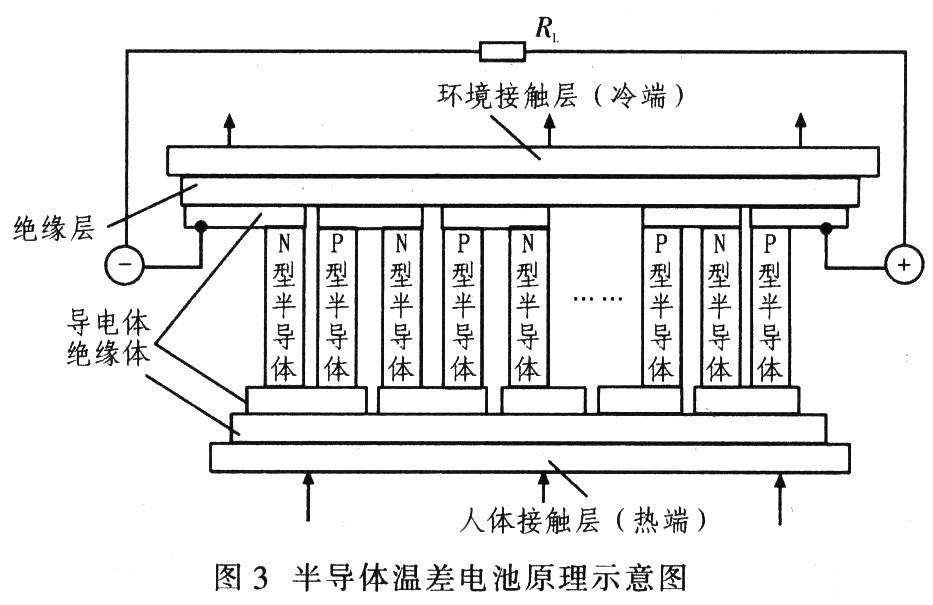
The main parameters describing the thermoelectric conversion performance of semiconductor temperature difference batteries are power generation efficiency and output power. When the load resistance RL and the resistance R of the temperature difference battery itself match, the load can obtain the maximum output power from the semiconductor temperature difference battery, and the material's figure of merit Z is important for the power generation efficiency and output power of the semiconductor temperature difference battery, and Z Mainly related to the nature of the semiconductor galvanic arm. For the temperature difference galvanic couple with a certain temperature difference and electrical characteristics, the figure of merit is not a constant, but is related to the geometry of the thermocouple. When the length of the galvanic arm is less than 1 mm, both the output power and the power generation efficiency increase with the length of the galvanic arm. When the length exceeds 5 mm, the output power and power generation efficiency tend to be constant. The thermocouple is formed by polysilicon, and the thermopile is formed in series. The boosting device with a low starting voltage of 0.8 V can calculate the body temperature. The charging device needs about 809 thermocouples to charge the mobile phone, and these thermocouple arrays are connected in series. Make up a thermopile. Assume that the temperature difference between the environment and the human body is 9 ° C, the conversion efficiency is 15%, and only human skin with an area of ​​about 0.012 721 m 2 is required, that is, only 1/158 of the total skin area of ​​the human body is used. In order to meet the charging requirements of mobile phone lithium-ion batteries, it is necessary to further increase the voltage and current generated by the temperature difference. The semiconductor temperature difference batteries can be connected in series and in parallel to form a temperature difference battery pack, and the semiconductor temperature difference battery is used as a power source, and the series-parallel connection and other power sources are used. There is no essential difference between series and parallel.
A P-type semiconductor and an N-type semiconductor material are plated on a substrate on a rectangular insulating substrate using a thermopile production process to form a unit containing hundreds of thermocouples, and a connection point is plated at both ends thereof. A thermopile (temperature difference battery) is formed, and a plurality of thermopiles are connected in series to form a thermoelectric battery pack, and the leads are soldered to the boost regulator circuit module.
There is a certain gap between the thermopile of the semiconductor temperature difference battery pack. The gap is a wicking hole provided for the comfort of the equipment. The temperature difference battery pack is sewn on a special vest or inside the hat, and is worn on the body to allow the thermocouple. The hot end face is close to the skin, and the cold end face is exposed to the air. At this time, the DC generating module starts to input the m voltage.
3.2 boost regulator module
The temperature difference between body temperature and the external environment is small, the voltage generated by the thermocouple is also small, and 4.2 V is required for charging the mobile phone. If all are converted by thermocouple, many thermocouples are needed. A boost device can solve this problem.
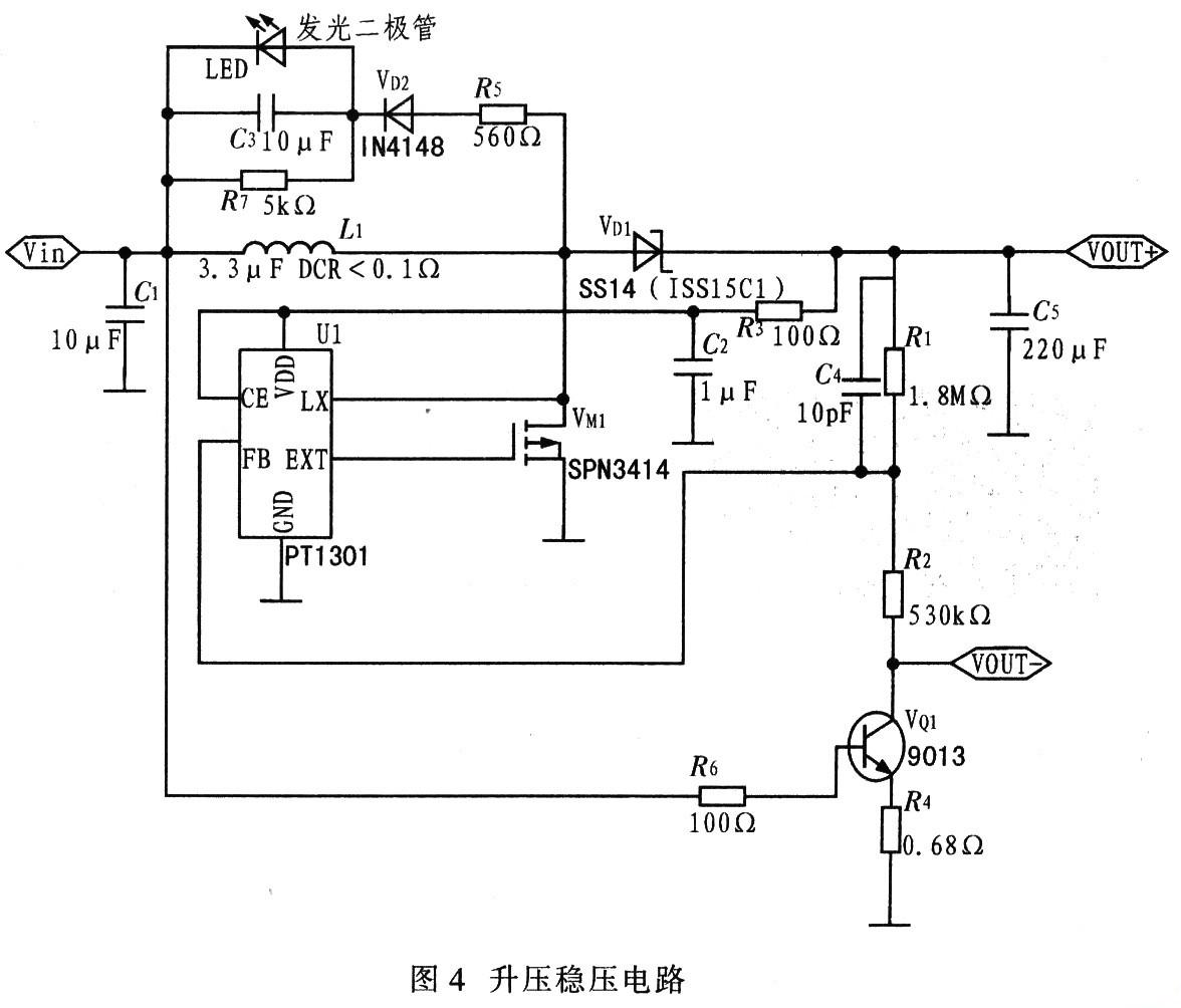
According to the Seebeck effect, the temperature difference between the two sides of the DC generating module is unstable, and the output voltage is also unstable. Because it is difficult to control the ambient temperature (the temperature of the cold junction) to a fixed value, the output voltage needs to be regulated before it can be sent to the mobile phone. According to the charging requirements of the mobile phone, the step-up DC/DC converter device PT1301 is selected to implement the boost regulator circuit, as shown in FIG. The output voltage is set by two external resistors, ie
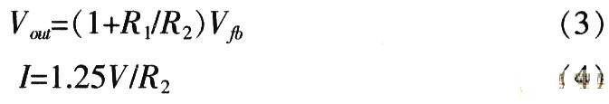
Adjust the resistance of R1 and R2 so that the output voltage U0 is stable at 4.2 V and the output current is 160 mA.
4 mobile phone body temperature charging system process
A key part of the mobile phone body temperature charging system is the DC power generation module, which is mainly a thermopile formed by 809 semiconductor thermocouples. The manufacturing process of thermopile mainly involves the cutting and pre-processing of materials, as well as the overall welding assembly of components. According to the previous analysis, the manufacturing process of the thermopile has the following requirements: contact resistance and contact thermal resistance should be as small as possible; high reliability and strong mechanical endurance; easy to achieve good heat with the radiator and the human body surface Contact; as low a production cost as possible.
(1) Cutting and pretreatment of materials The most commonly used thermoelectric material Bi2Te3 and its alloy materials are prepared by melt growth method. Since such materials are characterized by extremely easy cleavage and anisotropy, when cutting the ingot into strip-shaped thermocouple arms of the desired aspect ratio, it is necessary to pay attention to the cutting direction of the material to make the thermocouple The length direction is along the growth direction of the material, thereby ensuring that the thermocouple is in the direction of maximum value. For smaller thermocouple arms, wire cutting or EDM cutting can greatly reduce material damage and cutting loss. However, the cutting rate is slower in this way.
Bi2Te3 and its alloys have an orthorhombic crystal structure, which is often difficult to weld with several commonly used tin-based solders, making it difficult to achieve direct soldering of thermocouples and baffles. A common solution is to hang a layer of transition solder on the end face of the thermocouple arm. Bi95Sb5 is usually used. In addition to selecting a solder with better contact performance, an appropriate process is required. Before welding, it is best to carry out chemical cleaning (corrosion method) on each welding surface. When welding, it is necessary to select the appropriate welding temperature and time, which can improve the conductivity and thermal conductivity of the thermopile joint to some extent.
(2) Assembly and soldering of devices The ceramic metallization technology is currently the most commonly used thermopile manufacturing technology. The technology uses a ceramic sheet with high thermal conductivity and good electrical insulation as a substrate. According to the thermopile guide sheet design, a partial metallization area is formed on the ceramic sheet by screen printing and high-temperature sintering, and then This region forms a copper baffle, after which the thermocouple arm can be soldered between the two ceramic sheets to form a thermopile. Commonly used ceramic sheets are alumina (Al2O3) and yttrium oxide (BeO). For general applications, alumina materials are often used.
5 test results
The DC power generation module converts the temperature difference between the cold surface and the hot surface into a voltage using a semiconductor temperature difference battery pack, and the test device is as shown in FIG.
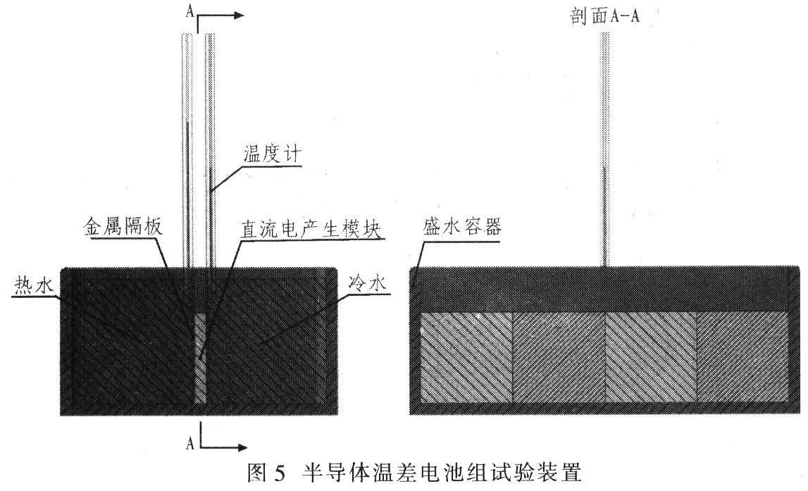
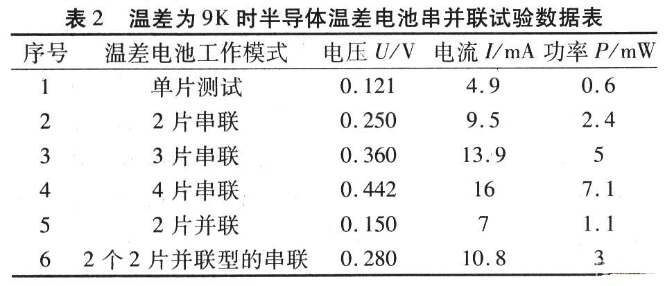
The water is heated on the hot side of the semiconductor temperature difference battery, and the cold surface is added with cold water to form a temperature difference between the two sides, so that the heat of the hot water is well transmitted to the semiconductor temperature difference battery pack, and the contact between the semiconductor temperature difference battery pack and the metal separator Apply a thin layer of thermal silica on the surface to remove the air from the contact surface, so that the surface of the thermoelectric battery is in full contact with the metal thermal barrier. The experimentally measured adjustable DC power supply is charged with a voltage of about 0.911 V when the booster device is charged to the mobile phone, and the current is about 70 mA, and the equivalent input internal resistance is 13.01 Ω. therefore. The test consisted of 127 pairs of NP semiconductor thermocouples composed of a thermoelectric cell. Its external dimensions are 40 mm × 40 mm × 4 mm, and the measured internal resistance is about 3.8 Ω. Four pieces of different series and parallel tests are used. The external load is a 15 Ω resistor, making it equivalent to a boosted device. To charge the phone. Figure 6 shows the test results at different temperature differences, and Table 2 shows the experimental data for a temperature difference of 9 K.

6 Conclusion
According to the theoretical analysis, the mobile phone body temperature charging system is designed. The test results show that the equivalent internal resistance and load resistance of the four semiconductor temperature difference batteries are matched in series, and the output power is the largest. The series connection of the semiconductor temperature difference battery can increase the voltage and current under the same temperature difference. To meet the startup conditions of the boost regulator circuit module to meet the mobile phone charging requirements. Theoretical analysis and experimental results have proved that it is feasible to use the body temperature to charge the mobile phone. As long as the conversion efficiency of the thermocouple is further improved, the true meaning of the mobile phone will be realized.
Digital Distribution Frame,Easy To Configure,High Quality Digital Distribution Frame,Easy To Configure Install
Shandong Qingguo Optical Fiber Co., Ltd. , https://www.qgfiber.com