
1 MAX1200 features
The new ADC is moving toward low power, high speed, high resolution, and the new pipeline architecture is an effective way to achieve high speed and low power ADC. The MAX1200 is the representative of high-speed, high-precision, low-power ADCs that use this new technology.
The MAX1200 is a 16-bit, monolithic integrated analog-to-digital converter with a sampling rate of up to 1Msps. Its internal CMOS integration circuit uses a fully differential multi-stage pipeline architecture with fast digital error correction and self-calibration to ensure Full sample rate with 16-bit linearity and 91dB non-stray dynamic range (SFDR), as well as good signal-to-noise ratio (SNR) and harmonic distortion (THD) characteristics. MAX1200 is mainly used in high-resolution image systems, scanners, digital communications, instrumentation and data reception; its main technical features are as follows:
â— Single power supply + 5V power supply;
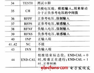
◠With ±VREF differential input, the forward reference voltage RFPF is provided by the external +4.906V voltage reference, and the negative reference voltage RFNF is connected to the analog ground;
â— When the input signal is 100kHz, the signal-to-noise ratio is 87dB;
â— The non-stray dynamic range when the input signal is 100 kHz is 91 dB;
â— The device consumes 273mW at 1Msps and +5V.
◠Differential nonlinearity error of ±0.5LSB;
â— Three-state, two-complement output is used;
â— With fast, controllable self-calibration function;
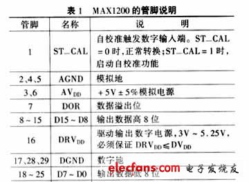
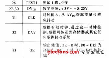
â— It adopts 44-pin MQFP package, and Table 1 is its function description.
2 Working principle
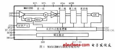
A pipeline ADC, also known as a sub-region ADC, consists of cascaded stages of circuitry, each stage including a sample/hold amplifier, a low resolution ADC and DAC, and a summing circuit. The sum circuit also includes an interstage amplifier that provides gain. Its fast and accurate n-bit converter is done by sub-zones (pipelines) divided into more than two segments. The sample/holder of each stage of the circuit samples the input signal and then quantizes the input by a coarse A/D converter with m-bit resolution, followed by a product-type digital-to-analog converter (MDAC) with at least n-bit precision. Generating an analog level corresponding to the quantized result and sending it to the summing circuit, then subtracting the analog level from the input signal by the summing circuit, and accurately amplifying the difference to a fixed gain and then delivering the next The stage circuit is processed. After such processing, the residual signal is converted by a higher precision K-bit fine A/D converter. Finally, the outputs of the coarse and fine A/D of the above stages are combined to form a high-precision n-bit output. It should be noted that these operations must satisfy the following inequalities in order to correct for overlapping errors:
l m+k>n
Where l is the number of stages, m is the coarse resolution of the ADC in each stage, k is the fine resolution of the fine ADC, and n is the total resolution of the pipelined ADC. Figure 1 shows the schematic of the MAX1200's 4-stage pipelined ADC and the internal structure of each stage, where m = 8, l = 4, and n = 16. Due to the mismatch between switched capacitors in the switched capacitor pipeline structure, the accuracy of the entire circuit is controlled by calibration and calibration logic. The four sampling processes of the pipeline structure introduce a wait time, that is, a pipeline delay, between the input signal being sampled and the data being output to D51-D0. However, continuous output can be obtained with continuous sampling. Figure 2 shows its data output timing diagram.
Digital Table Clock,Digital Clock,Nexie Tube Clock For Table,Table Clock Oak Wood
Guangzhou Huanyu Clocking Technologies Co., Ltd. , https://www.findclock.com