
Positioning systems refer to the localization and tracking of assets and personnel within a confined area, such as in buildings, campuses, ports, and warehouses. With the rapid growth of data and multimedia services, the demand for accurate positioning and navigation has significantly increased. As a result, positioning technology has emerged as a key industry and one of the most researched fields in the 21st century. Currently, common positioning technologies include infrared, ultrasonic, GPS, and Wi-Fi. However, these methods suffer from limitations such as limited coverage, poor resistance to interference, and low accuracy. To address these issues, this paper introduces an active RFID-based positioning system, which offers improved performance and is suitable for a wider range of applications.
**Analysis of Positioning Technologies**
Infrared positioning is only effective over short distances and is easily affected by ambient light sources like fluorescent or room lights. This limits its accuracy and applicability in larger spaces. Ultrasonic positioning, although capable of covering longer distances, is highly susceptible to multipath effects and non-line-of-sight conditions, making it unsuitable for indoor environments where obstacles are common. GPS, while widely used for outdoor positioning, relies on satellite signals that are weak indoors and cannot penetrate building structures, restricting its use to open areas. Wi-Fi positioning, though cost-effective and applicable in both indoor and outdoor settings, has a limited range of about 90 meters and is prone to interference, affecting its reliability and energy efficiency.
To overcome these challenges, this paper proposes an RFID-based positioning system. Compared to existing technologies, RFID offers lower costs, reduced environmental impact, high positioning accuracy, and extended coverage. It also allows for the retrieval of detailed information about the tagged objects.
**System Composition**
The active RFID positioning system described in this paper consists of four main components: the reader, the tag, the communication network, and the backend server, as illustrated in Figure 1.
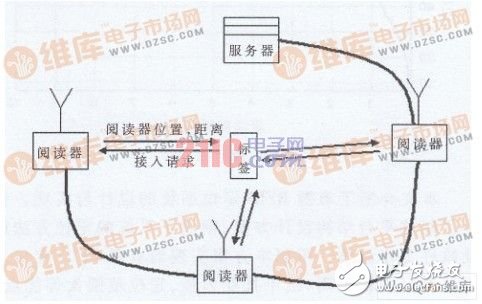
Figure 1: System Composition
Each reader stores its own location information and communicates with tags via radio frequency. The distance between the tag and the reader is measured using RF communication, allowing the system to calculate the position and send the data back to the reader. The communication network then transmits this information to the backend server, which can also control each reader remotely through the network.
Once installed, the tags can determine their own positions using radio frequency and upload the data to the backend server via the communication network. The server collects and processes the tag information, offering web-based services for real-time location tracking.
**Hardware Structure**
Both the tag and the reader share a similar hardware structure, consisting of a main controller, wireless RF transceiver and ranging module, antenna, and power supply system, as shown in Figure 2.
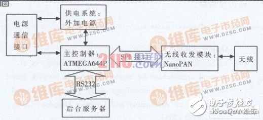
Figure 2: System Schematic
To meet the requirements for high-speed data processing and network communication, the system uses Atmel’s ATmega64 microcontroller. This chip features a Harvard architecture, single-cycle RISC instruction set, and internal hardware multiplication, enabling fast data processing. Its I/O ports can drive large current loads, and it supports online programming (ISP) and in-application programming (IAP), making it easy to update and debug the software. The system also includes a 16 MHz crystal for high-speed operation.
The wireless RF transceiver and ranging module employs Nanotron’s NanoPAN module, which uses Wideband Linear Frequency Modulation Spread Spectrum (CSS) technology based on IEEE 802.15.4a standards. Operating at 2.4 GHz, it provides data rates ranging from 31.25 kbps to 2 Mbps and achieves ranging accuracy of 1–2 meters. It supports reliable data communication and reduces the need for complex microprocessor configurations.
The antenna is designed with direct matching and includes ferrite shielding to minimize interference from metal objects and electromagnetic shielding to reduce the magnetic field generated by the antenna coil. A shielded antenna requires at least four layers on the PCB, with non-closed loops on the top and bottom layers to enhance electromagnetic compatibility.
FPV Drones 7 10 13 Inch Heavy Payload Long time Flight with Night Vision Camera Racing FPV Drones,I hope this drone can bring you passion and happiness. Please do not use it for war
FPV uav used for throwing,Night Vision Camera Racing FPV Drones,Customized Throwing FPV drone,FPV Unmanned Aerial Vehicle Used for Throwing
Jiangsu Yunbo Intelligent Technology Co., Ltd , https://www.fmodel-ai.com