
1 Introduction:
This article refers to the address: http://
At present, LCD TV is rapidly entering the family with its advanced technical performance, beautiful appearance, stable operation and high reliability. It is expected that in the next few years, LCD TV will be the mainstream product in the digital TV era. With the increasing use of LCD TVs, the consumption of electric energy is also increasing, and the pressure on energy conservation and environmental protection has increased dramatically. Therefore, the need to improve the energy efficiency of LCD TV switching power supplies is becoming more and more urgent. To this end, many government agencies and industry organizations around the world have developed new power consumption specifications for different sizes of TV sets, such as the US "Energy Star 3.0" standard and the German "Blue Angel" standard. Improve the efficiency of power consumption and reduce power consumption. The author will explore how to optimize the design of PFC stage, main DC / DC stage and standby converter, in order to better improve the energy efficiency of LCD TV switching power supply, to meet the new power consumption standards.
2 LCD TV power management system structure:
To improve the energy efficiency of LCD TV switching power supply, it is very important to analyze the structure of the LCD TV power management system, analyze the source of power loss, and take measures to reduce energy consumption.
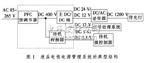
Usually, the LCD TV power management system consists of a power supply unit, a DC/AC inverter, and a signal processing system. The typical structure is shown in Figure 1. The power supply unit consists of a PFC pre-regulator, main DC/DC stage and standby converter for converting the AC input voltage (85~265 V) to a lower DC output voltage (24 V, 12 V, 5 V and 3.3). V), where the 24 V or 12 V DC voltage of the main DC/DC stage output is used to power the backlight inverter and signal processing system, and the 5 V or 3.3 V DC voltage of the standby converter output is the standby component and microcontroller powered by. The DC/AC inverter is responsible for converting the 24 V or 12 V DC voltage to a high AC voltage (eg 1 200 V AC) to power the backlight. Signal processing systems are used to control and process sound and image signals.
According to ON Semiconductor Co., Ltd. ("Ansonmei"), the PFC-class loss and main DC/DC loss of the LCD TV switching power supply are the main losses of the LCD TV switching power supply, and the PFC-class loss accounts for about 40 of the total power loss. %, the main DC/DC stage loss accounts for approximately 60% of the total power loss. To this end, I will optimize the design of the PFC stage and the main DC/DC stage to reduce the power consumption of both, while designing the standby converter to meet the new power consumption specifications of switching power supply standby power consumption should be less than 1 W. standard requirement.
3 PFC pre-regulator solution:
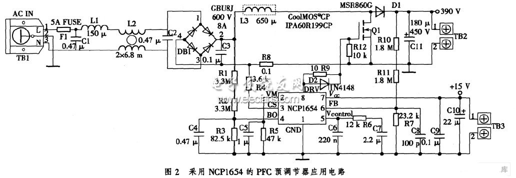
In order to reduce the power consumption of the PFC stage and achieve the energy efficiency improvement target of the PFC level, it is necessary to consider the topology and the working mode of the PFC controller. From the perspective of the complexity of the design and the total cost of the power solution, the best solution is: the topology is Boost boost structure, and the PFC controller works in continuous conduction (CCM) mode. For the CCM mode of operation, the PFC controller can choose the solution provided by ON Semiconductor or Infineon Technologies AG (“Infineonâ€), which can achieve a power factor higher than 93% and meet the ICE61000-3-2 standard requirements. . However, if we consider a variety of factors such as cost performance, reliability and high power factor, choosing the PFC controller NCP165 4 from ON Semiconductor is a more reasonable solution. The use of this controller requires very few external components, which makes the design of the PFC stage more compact. This controller has extremely low power consumption and can meet the requirements of improving PFC-class energy efficiency. It also features fast transient response, low starting current and low shutdown current. It has many safety protection features such as inrush current detection. Overvoltage protection, undervoltage detection for open loop detection, soft start, precise overcurrent limit, true overload limit, etc. In summary, it integrates all the features needed to build a compact and robust PFC. In addition to the controller section, choosing a new CP Series Cool-MOS switch with low on-resistance and low parasitic capacitance and a soft recovery boost diode are also the best choice for efficiency. In summary, the PFC converter circuit in the LCD TV switching power supply is shown in Figure 2.
Primary DC/DC level solution #e#
4 main DC / DC level solution:
Quasi-resonant (QR) mode is currently the best solution for improving the efficiency of the main DC/DC stage. The QR mode responds quickly to load changes and is ideal for changing the load from the lowest (or even zero) to the maximum rated power. It can achieve zero voltage turn-on of the switch, which effectively reduces the current spike during turn-on and reduces turn-on. The EMI noise caused by current spikes increases efficiency.
In the QR theory, when the power rating is less than 200 W, it is recommended to use a quasi-resonant flyback topology in the DC/DC stage; when the power rating exceeds 200 W, an LLC resonant converter can be used. However, in practical applications, in order to better balance performance and cost, designers often use quasi-resonant flyback converters with appropriate control chips as the preferred solution for the main DC/DC stage.
At present, the commonly used quasi-resonant flyback converter control chips are ON Semiconductor's NCP1337, STMicroelectronics' L6566, Angbo's OB2202 and OB2203, and Infineon's ICE2QS02G. Among them, NCP1337, L6566, OB2202 and OB2203 are used in low-power LCDTV switching power supplies, and their cost performance is similar. The ICE2QS02G can be applied not only to small power applications, but also to medium and high power applications. In addition, it is also superior to other chips in terms of cost performance. For this reason, in the quasi-resonant flyback converter scheme, the author chose ICE2QS02G as the control chip.
The ICE2QS02G has digital down-conversion technology, which reduces the switching frequency as the load decreases. At the same time, the controller can turn on the MOSFET at different valley points according to the load, so that the switching loss and conduction loss of the converter are always Balanced, the converter achieves maximum operating efficiency and the system's average efficiency is greatly improved. In this case, it can solve the following problems in the free-running operation of the conventional quasi-resonant flyback converter (only with the maximum frequency limit): when the system load is in the full load range (50%~70%), the switch The frequency will increase a lot, making the designer have to work hard to achieve a balance between cost and optimized design. In addition, the ICE2QS02G features a variety of user-adjustable protection features designed to protect the system and make the IC suitable for different applications. In fault mode, such as open loop control loop/overload, output overvoltage, and transformer winding short, the device will switch to auto-restart mode or latch mode. By using cycle-by-cycle peak current limiting and foldback correction, the transformer size can be reduced and the current level of the secondary diode can be optimized to increase the cost efficiency of the design.
In summary, the main DC/DC stage uses a quasi-resonant flyback converter and the corresponding control chip ICE2QS02G is a good solution. In addition, high-voltage MOSFET switching transistors (such as the new 800 V CoolMOS C3 series switching transistors) can be used in the quasi-resonant flyback converter to reduce the main conduction loss and the conduction loss of the MOSFET, which can increase the efficiency by 1%~3. %, which improves the efficiency of the main DC/DC level.
5 standby converter solution:
Under the new power specification, LCD TV switching power supply standby power should be less than 1 W. In this case, the output power is very low or even zero, the output current of the system is close to zero, the conduction loss of the MOSFET and the diode and the core loss are negligible, and the turn-off loss of the secondary measurement diode and the turn-on loss of the MOSFET can also be Ignore, the main losses in standby are the MOSFET turn-off loss and the start-up resistor loss. Therefore, reducing these two losses is a key point in reducing standby power consumption and designing a standby converter. Currently, the designer's preferred solution is to design a stand-alone standby converter with a fixed frequency flyback topology and its corresponding control chip in the standby converter.
In terms of reducing the starting resistance loss, the conventional method mostly reduces the starting current and increases the starting resistance, but the effect of the method is not obvious. To this end, Infineon proposes a method of replacing the resistor with a switching circuit. During the startup process, the startup circuit is turned on, and when the IC is activated, the startup circuit is turned off. Practice has proved that this method can eliminate the loss of the starting resistor. Infineon's CoolSET F3 chip integrates such circuitry to reduce power supply losses.
In terms of reducing the MOSFET turn-off loss, since the MOSFET turn-off loss is proportional to the switching frequency, the lower the frequency, the smaller the loss. However, from the basic principle of switching power supply, in the normal operating mode, it is necessary to use high frequency to reduce the size of devices such as transformers and filters, while in standby mode, low frequency is beneficial to reduce losses. Therefore, an integrated power IC with automatic down-conversion technology should be used in the standby converter solution. In the normal load range, the IC operates at high frequencies, and when the output power drops to a certain threshold, the IC will automatically reduce the switching frequency.
In terms of "automatic frequency reduction technology", there are currently more common methods such as pulse skip mode, abrupt mode and non-conduction time modulation. Among these methods, the active abrupt mode introduced by Infineon has the best performance, which maintains output regulation and prepares for load fluctuations when the system is in standby. In this regard, combined with the complexity and cost of the design, the standby converter chooses Infineon's latest ICE3BR4765J is a good solution. The ICE3BR4765J has a unique active abrupt mode, plus a Bi-CMOS manufacturing process that enables the product to achieve a very low standby power consumption, such as a 25 mW standby on a 12 W/5 V product. Power consumption. The ICE3BR4765J adds ±4% of frequency jitter to the fixed switching frequency, reducing overall EMI levels, reducing the user's additional filter requirements and production costs. The ICE3BR4765J integrates a 650 V start-up unit, which greatly simplifies peripheral circuit setup and reduces system cost.
Based on the above analysis, the optimized standby converter solution is: independently designed flyback standby converter, and adopts Infineon's latest integrated power IC chip ICE3BR4765J.
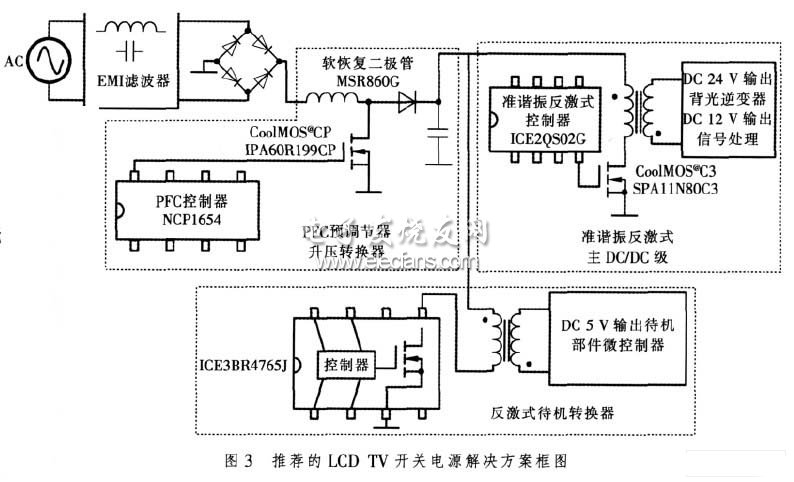
Based on the above PFC stage, main DC/DC stage and standby converter solutions, the block diagram of the LCD TV switching power supply solution shown in Figure 3 can be designed.
6 system performance analysis:
Based on the above power solution, an LCD TV switching power supply is designed. The technical specifications are as follows: 1) The input voltage is AC 85~265 V; 2) The input frequency is 47-63 Hz; 3) The input harmonic is in accordance with EN61000. -3-2 standard; 4) The main DC/DC stage output is 24 V/6 A, 12 V/3 A in normal operation, 5 V/2 A in normal operation; 5) Standby operation at 5 V/ The pin consumes less than 1 W at 0.1 A output.
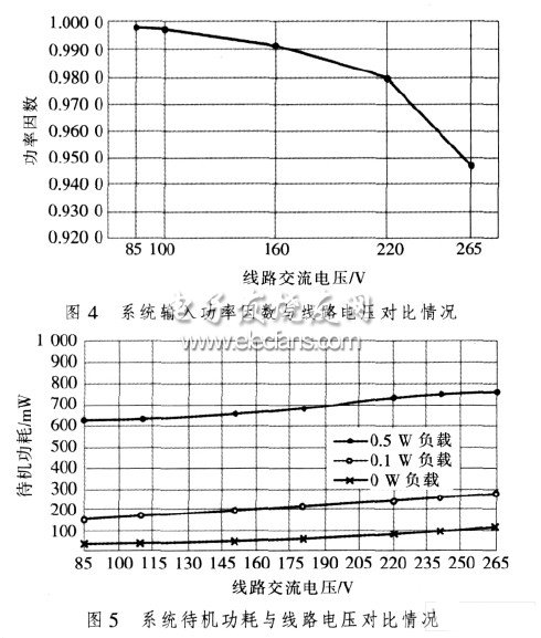
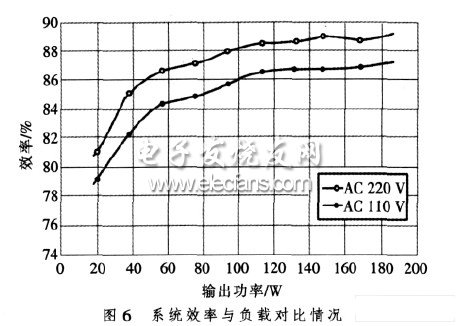
System performance was tested under the above technical indicators. Figure 4 shows the comparison of the system input power factor to the input line voltage under full load conditions. It can be seen from Figure 4 that the power factor is higher than 94% under different input line voltage conditions, and the system has a high power factor. Figure 5 shows the system standby power consumption under different load and line voltage conditions. As can be seen from Figure 5, the system input power is low during standby, meeting the requirements of Energy Star 3.0. Figure 6 shows the system efficiency for different load conditions at rated line input voltage. It can be seen from Figure 6 that the system full load efficiency exceeds 87% and the system average efficiency is high.
7 Summary
The energy efficiency challenges faced by LCD TV switching power supplies are becoming more and more severe. To meet these challenges, a combination of an active PFC pre-regulator, a quasi-resonant flyback main DC/DC converter and a separate flyback standby converter can be used. In the solution, the PFC controller NCP1* from ON Semiconductor, the ICE2QS02G quasi-resonant flyback controller from Infineon, the integrated power chip ICE3BR4765J and the CoolMOS switch tube are selected to make the design cost-effective.
Support the camping pot selection of 26 national standard cast iron, safe without coating, the depth of iron, iron than other pots to enhance the effect of 20%, because the support of camping pot unique shape, heat collection capacity, cooking faster than other Pot to enhance the 40%, thicker process, better insulation, pottery than about 25% energy saving, the original ecological cast iron pot, so that food taste better, to retain the original flavor of food, tasty effect increased by 50%
Support the camping pot and the so-called non-smokeless pot, non-stick pot compared to its unique pot-free coating design from the fundamental to eliminate the chemical coating and aluminum products on the human body harm, while maintaining the nutritional content of the dish is not destroyed To make the whole family enjoy the health and delicious.
Camping Cookware,Camping Cookware Pans,Camping Aluminum Cookware,Portable Camping Cookware
Ningbo APG Machine(appliance)Co.,Ltd , http://www.apgelectrical.com