
With the advent of more and more portable audio devices such as DVDs, MP3s, MP4s, and smart phones, the board design space for these devices is becoming increasingly scarce. Nowadays, it is increasingly important to design the size of the solution according to a specific function and to minimize the number of components required under the expected function. The transmission of audio signals to headphones has always used DC blocking capacitors. In addition, other alternative solutions are not inherently limited, too simplistic and unrealistic, and are not recognized and accepted by the market.
This article focuses on the headphone amplifier architecture. In addition to explaining its advantages and disadvantages, it also introduces a new solution that solves the problems caused by some headphone amplifier architectures.
Different headphone amplifier configurations
One of the traditional methods of driving a headset without a large DC blocking capacitor is to offset the ground pin of the connector to the neutral rail, which is VDD/2 (VBIAS). Since most consumer headphone amplifiers are single-supply, the only way to achieve good dynamic range is to offset the audio to VDD/2 with DC, allowing the signal to swing to ground and VDD. Since the ground pin is connected to VDD/2, the main disadvantage is that the grounding circuit problem is caused by an external device connected to the Hi-Fi amplifier or the power-driven speaker, such as a grounded ground (ie, 0V). And cause unnecessary noise or design problems.
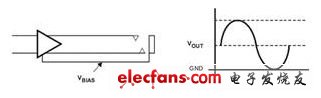
Figure 1. Output single-ended headphone amplifier with offset grounding sleeve
As shown in Figure 1, the most traditional headphone amplifier architecture is a single-ended amplifier with DC blocking capacitors.
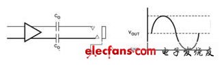
Figure 2. Single-Ended Headphone Amplifier with DC Barrier Capacitor
It can be seen that the output of the headphone driver is shifted to VDD/2 (VOUT), and the audio swings from VDD to ground. A DC blocking capacitor is required to remove this bias and allow the signal to swing around ground, that is, between –VDD/2 and +VDD/2. The advantage of this architecture is the ability to use standard earphone jacks. However, the main problem with this type of approach is the low frequency response. The headphone impedance is typically 16Ω or 32Ω, and both the output capacitor and the headphone horn impedance form a high-pass filter with a cutoff frequency of 3dB, as shown in Equation 1:

(Equation 1)
The cutoff frequency must be within the audio band of the headset. This band varies from manufacturer to manufacturer, but the general range is between 20 Hz and 20 kHz. In order not to attenuate the low audio frequency, the cutoff frequency of the high pass filter must be at least about 500 Hz.
Rewriting Equation 1 to Equation 2 yields:
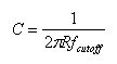
(Equation 2)
For a 100 Hz cutoff frequency and a 16 Ω headphone horn impedance, the capacitor must be 110 μF. In the case where a small volume size is required, this causes the capacitance value and the physical size to be too large, and the cost is too high. Many engineers can only switch to a smaller 22μF capacitor, but this can affect the low-frequency fax of the headset, resulting in poor bass response.
Various implementations have their advantages and disadvantages, but for designers who need better audio and avoid potential ground loop problems or large DC blocking capacitors, a newer architecture called grounded or "no capacitance" begins. Highly noticed.
Candle Chandelier is used in living room, lobby, dinning room, Wedding center. Those materias usually is glass, metal, crystal, Zinc-alloy or Brass, Luxury nice
Candle Chandelier
Candle Chandelier, Crystal Chandelier, Glass Chandelier
Zhongshan Laidi Lighting Co.,LTD , http://www.idealightgroup.com