
Design of Car Digital Video Compression Recording System Based on LPC2210 and SZ1510
In recent years, the rapid development of computer technology, multimedia technology and data communication technology has promoted the application of digital video more and more (such as video surveillance, video conferencing and mobile TV, etc.). Subsequently, the study of various compression algorithms made the storage and transmission of digital video extremely convenient, and various video recording systems also appeared one after another. The embedded video recording system designed in this paper can convert the analog video data captured by the camera into digital video data, store it in a large-capacity memory after compression, and can reproduce the entire process of the car's exercise through a dedicated playback device. The video recording system can be used to record video information and emergency event markers such as various instruments in the car and the front view, and it can continuously and dynamically record all information in the process of the car in digital video. This system can be combined with the car black box to facilitate the management department to effectively manage the vehicle according to the relevant data recorded, and it can also provide an accurate basis for the analysis after the accident and determine the true cause of the car accident. At the same time, it is possible to analyze and improve the bad driving habits by recording and viewing the driving data such as whether it is usually urgently accelerating or braking, so as to prevent accidents.
Common video compression methods include MPEG series and H.26X series. Considering the maturity, cost and main use of compression technology, this recording system adopts MPEG-1 digital image compression recording technology to realize real-time loop recording of continuous images of 1 channel video signal for up to 4 hours. In addition, the video recording system also has the characteristics of low cost, small size and low power consumption.
1 Working principle of the system
The focus of the video recording system design is to reduce costs, reduce volume, and at the same time reduce system power consumption and improve the overall performance of the system. It can record up to 4 hours of continuous real-time dynamic loop recording of one video signal on the car. This system is mainly composed of video decoding and compression encoder, ARM processor and electronic disk. The video decoder and the compression encoder together form a compression unit, the ARM processor is the control unit of the system, and the electronic disk is the storage unit of the system. The structure of its video recording system is shown in Figure 1. When the system is working, the video signal captured by the camera is first decoded and A / D converted by the video decoder SAA7113H to output the YCbCr digital video signal in 8-bit 4: 2: 2 format, and the digitized video signal is sent to the SZ1510 compression encoding After the chip is compressed, an MPEG-1 data stream can be generated, and then the ARM processor stores the compressed data into the storage carrier-the electronic disk through the IDE interface, so as to realize continuous real-time loop recording of 1 channel video signal.
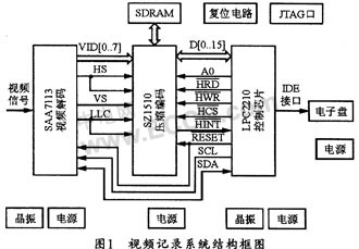
After the system is powered on and started, the ARM processor first configures the internal registers of the SZ1510 through the HOST interface of the SZ1510 chip, and initializes the video decoder SAA7113H through the I2C bus. After setting the MPEG-1 compression format and data rate, the system starts to work normally, and the input analog video signal is decoded and A / D converted by the video decoder, and then the generated CCIR-601 digital video stream is compressed and encoded. The chip SZ1510 is processed, and then the SZ1510 converts the digital video data into a movie file conforming to the MPEG-1 format, and finally writes the MPEG-1 data stream to the electronic hard disk as a file through the IDE interface under the control of the ARM processor for storage. When the system is working, ARM will continue to monitor the relevant signals and add corresponding signs to the image until the shutdown signal is received, the system automatically ends the compression work.
2 Hardware circuit design
2.1 Video decoding and compression coding circuit design
Because the MPEG-1 compression algorithm requires a large amount of calculation, it is difficult to complete in real time with software, so this system uses a dedicated video compression chip to achieve real-time efficient compression of video signals. At present, commonly used MPEG-1 compression chips are VW2010, W99200F, WIS 7007SB and so on. This design selects SAA7113H for decoding, and uses Zapex's SZ1510MPEG-1 A / V encoding chip for image compression. The main function of SAA7113 is to decode the input analog video signal into a standard 8-bit "VPO" digital signal. It is equivalent to an "A / D" device and is a programmable video processing chip that can be implemented through the I2C bus. Programming control, and has 4 video input, anti-aliasing filtering, automatic clamping and gain control, multi-standard decoding and brightness, contrast and saturation control. It samples and decodes the input PAL video signal , The generated CCIR-601 digital video stream (color space is YCbCr, sampling is 4: 2: 2) can be sent to the digital video input interface of the video compression chip SZ1510. Its input clock is provided by an active crystal oscillator of 24.576 MlHz , And can output line sync signal HS and field sync signal VS provided by SZ1510 from RTS1 and RTS0 pins respectively, where line sync signal HS can also be input as line effective pixel identification signal to VIHACT pin of SZ1510; and from LLC The pin outputs a 27 MHz pixel clock, which is used as the sampling clock of the digital video stream in the SZ1510 and the main clock of the chip. The system initialization can be achieved through the I2C bus of the ARM chip. Chip select signal ARM generating RESET signal is provided.
The compression encoding chip SZ1510 in the system is a high-performance MJPEG and MPEG-1 encoding chip produced by ZAPEX, which can compress video signals up to 25 f / s, and supports multiple working modes and bit rate modes. The mode combination can be flexibly realized, and the video mark and time mark can be superimposed on the video at the same time. The chip is mainly composed of video coding core, TMS320C54X high-performance DSP core, interface circuit (video interface, memory interface, host and serial interface), DMA controller and clock generation circuit. The internal compression core has been optimized for high-efficiency, real-time MPEG-1 digital image compression, and has many features, low power consumption, wide temperature range and other characteristics.
The SZ1510 in the system is a slave device, controlled by the host ARM. Its HOST interface is the interface for control and data exchange. SZ1510 can choose a variety of bus types, it has multiplexed and non-multiplexed Intel and Motorola bus types (in multiplexed mode, HAD [7: 0] can be used as a data line, but also as an address line; non-multiplexed mode At that time, HAD [7: 0] can only be used as a data line), the non-multiplexed bus can be divided into 8-bit and 16-bit, and can be selected and configured by the HCONFIG [l: 0] pin and Syscofig [3] register. This system sets HCONFIG0 low, HCONFIG1 high, and Sysconfig [3] writes 1, so it can work in Intel 8051 type non-multiplexed 16-bit data bus mode.
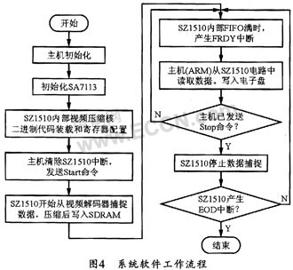
Because SZ1510 has multiple working modes, according to system requirements, this design makes SZ1510 work in LVE (Live Video Encoding) real-time video encoding mode. In this mode, SZ1510 can obtain real-time digital video data from the video decoder, and then compress it according to MPEG1 / M-JPEG and pass it to the host computer. The specific work process is: SZ1510 passes the CCIR-601 digital video stream input to it through video preprocessing, automatic cropping, scene change detection, motion estimation, motion compensation, discrete cosine transform / inverse discrete cosine transform and variable length coding, etc. After processing, the generated MPEG-1 video elementary stream is stored in SDRAM, and then the data is output through the FIFO buffer with a size of 256 bytes at the output port. In normal operation, a FRDY (FIFO read) interrupt is generated every time the FIFO is full to notify the host to read the data in the FIFO, and the host reads the data from the Data_out register. After that, when the SZ1510 issues an EOD (End of Data) interrupt, the data transfer ends.
In the video compression working mode, SZ1510 has 3 output bit rates to choose from: constant bit rate, maximum bit rate, and variable bit rate. The constant bit rate requires padding redundancy, the maximum bit rate does not require padding redundancy, and the compression quality of the variable bit rate is variable compared to the constant bit rate. The selection of bit rate can be determined by setting bits 1 and 2 of the Ven_cntl register. When it is 0, the constant bit rate is selected; when it is 1, the maximum bit rate is selected; when it is 3, the variable is selected Bit rate.
2.2 Control and storage circuit design
Considering the volume, reliability and control capability of the control part, the CPU in this system uses the ARM7TD-MI-S core microcontroller LPC2210 of Philips. This is a 16 / 32-bit ARM7TDMI-S CPU that can support real-time simulation and tracking. For applications where the code size is strictly controlled, the 16-bit Thumb mode can be used, which can reduce the code size by more than 30%, but the performance loss is very small. The LPC2210 uses a 144-pin package and has extremely low power consumption. In addition, the chip also has multiple 32-bit timers, 8 10-bit ADCs, PWM outputs, and up to 9 external interrupts. By configuring the bus, the LPC2210 can provide up to 76 GPIOs.
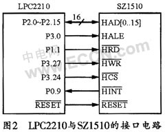
The LPC2210 can be connected to the HOST interface of the SZ1510, and the SZ1510 can be controlled and set through the HOST interface. During normal operation, the LPC2210 sends the MPEG-1 format video stream output from the HOST interface as a file to an electronic disk for storage. The interface circuit of LPC2210 and SZ1510 is shown as in Fig. 2. Among them, HAD [0… 15] is connected to P2.0 ~ P2.15A of ARM as 16 data lines; P3.0 is connected to HALE pin to realize SZ1510 internal IOAR (I / O Address Registerl) and IODR (I / O DataRegister) register selection; P1.1 and P3.27 respectively access the read and write strobe pins HRD and HWR; select SZ1510 by connecting P3.24 to HCS; send SZ1510 interrupt by connecting P0.9 to HINT Request signal.
From the perspective of weight and reliability, this recording unit is finally implemented with an electronic disk. The main body of the electronic disk is a Flash chip. The chip is impact resistant, high temperature resistant, small in size, long in life, and suitable for working in an automotive environment. Although the price of the electronic disk is expensive, considering that the system only collects one video signal, the amount of recorded data is not very large (after calculation, the capacity of the recording unit is 3G), the recording length can reach 4.5 hours, so, The choice of electronic disk can fully meet the task requirements.
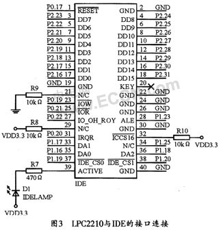
The connection circuit of GPIO pin of LPC2210 and IDE interface is shown as in Fig. 3. In the figure, P2.16 ~ P2.31 are the data lines, P1.16 ~ P1.20 are the address and strobe signals, P0.17 and P0.20 are the device reset and status request signals, use P0.21 and P0 .19 can achieve read and write control.
3 System software design
All software programs of this system should be burned into ARM through the JTAG port in advance, so that these programs can be automatically run after the system is powered on to control the work of the system. The system software work flow chart is shown in Figure 4.
3.1 SZ1510 register configuration
The SZ1510 has 128 registers, each of which has an index number. The external host sets the two registers IOAR (I / O address register) and IODR (I / O data register) inside the SZ1510 through the HOST interface (HALE pin). ) To control and configure the SZ1510. When accessing, first send a low level from the A0 pin of the host to the HALE pin to select the IOAR register, and then write the index number of the register to be accessed into the IOAR; then send a high level from the A0 pin of the host to the HALE tube To select the IODR register, and then write the data to be written to the IODR, so that the SZ1510 will automatically send the configured data to the register at the specified address.
When initializing Z1510, the host first writes any value to the 0x0B register; then after the host waits at least 1 microsecond, write 0x40 to the Int_enable interrupt enable register to enable the RDY (Ready) interrupt; then, the host waits SZ1510's Ready (Int_source [6]) interrupt; after that, when the host waits for the RDY interrupt, it will clear the RDY interrupt and start loading binary code into the SZ1510's internal DSP.
3.2 Binary code loading of SZ1510
Since the content of the internal register is unknown after reset, the host must load the program code to initialize the programmable RAM of the video encoding core. The program space inside the SZ1510 is divided into blocks (Blank), and the size of each block is 256 bytes. The loading space of the binary code used for the video encoding core is six blocks of 0x000 to 0x004 and 0x00c, and a total of 1.5k bytes of code. When loading specifically, the host first writes 0x01 to the 0x2E register to indicate that the external SDRAM is 1M × 16bits; then the host writes 0x03 to the 0x0C register to enable the FIFOReady and End of Data interrupt; then the host writes 0x1 to the 0x11 register , Set the working mode as the internal memory write mode; then the host writes 0x20 to 0x10, to set the FIFO size of the SZ1510 output data to 256 bytes; finally load the binary code of each program space, the specific process is as follows:
(1) The host writes 0x3F register and selects the download program space;
(2) The host writes 0x04 to the 0x08 register and sends a start command;
(3) The host waits for Ready interrupt;
(4) The host clears the Ready interrupt by reading the 0x0e register;
(5) The host writes 256 bytes to the Data_in register 0x01;
(6) The host waits for EOD (End 0f Data) interrupt,
(7) The host clears the EOD interrupt by reading the 0x0e register;
(8) The host checks whether the code in the program space has been loaded, and if not, continues to load.
4 Conclusion
The system can record the video signals displayed by the cameras outside the car and the instruments in the car for a long time in real time. The recorded compressed data stream conforms to the MPEG-1 image compression standard. The compressed video flow rate used in this design is 1.5 Mbps. For a 3GB electronic disk, this system can continuously record more than 4.5 hours of car video data. This shows that the system is small in size and low in power consumption, which is convenient for real-time and long-term compressed data recording of video data in a mobile environment.
1.Block your Webcam with a C-SLIDE. Stop's Webcam Spying
2.Can silk printing with your LOGO. Simply attaches with double sided adhesive that can be removed later.
3.Fits: Computers, Laptops, Smart TV's, PS4, Xbox, 3rd party external webcams
4.Protects your webcam from scratches. Made from high-grade durable ABS.
5.cheap price custom logo camera Webcam Cover for laptop computer
Webcam Cover
Webcam Cover,Camera Cover,Laptop Webcam Cover, Laptop Metal Camera Cover
Custom Usb Gift company limited , https://www.customusbgift.com