
Development of Remote Control Stimulation System of Constant Current Multi-channel Animal Robot
An animal robot is a robot that uses animals in nature as a moving body. Micro-electrodes are implanted in the brain nucleus or direction sensing area related to animal movement, and artificially simulated nerve electrical signals are applied to achieve the purpose of controlling animal movement. Compared with biomimetic robots, animal robots are valued by powers in the world because of their better environmental adaptability, concealment, flexibility and reliability of movement. In recent years, the research work on animal robots at home and abroad has been booming. Scientists have carried out research and development on robot cockroaches, robot mice, robot turtles, robot pigeons, and robot geckos, and have achieved many exciting results. In 2001, Professor Isao Shimoyama of the University of Tokyo in Japan equipped cockroaches with an "electronic backpack". With proper stimulation, cockroaches could turn left and right according to the instructions; in 2002, Nature magazine reported on the State University of New York Medical Center. Professor Chapin implanted electrodes into different brain regions of rats, and under the stimulation of artificial analog electrical signals, controlled the rats to walk according to the pre-designed route; in 2007, the Robot Research Center of Shandong University of Science and Technology initially realized the control of pigeons according to humans. Command flight, becoming the world ’s first robot bird III; the Institute of Bionic Structure and Material Protection, Nanjing University of Aeronautics and Astronautics, selected the large gecko with special sports capabilities as the research object, and took the lead in launching The artificial induction study measured the spatial distribution of the gecko's brain area and movement-related nuclei, revealed the spatiotemporal coding law of the gecko's neural electrical signals, and successfully realized the basic movements of the gecko's left turn, right turn, forward and avoidance. Artificial induction of behavior.
Among the many factors that determine the success of the development of animal robots, "animal robot remote control stimulation system" is one of the key factors. It is the only way for animal robots to get rid of various restraints and achieve free movement. It is also the signal that animal robots throw away Line, the necessary conditions to get out of the laboratory. It requires reliable operation, low energy consumption, high efficiency, and long transmission. In order to accurately control animals with individual differences, the remote control stimulation system also requires independent adjustment of various electrical stimulation parameters. In addition, it is affected by animal posture and animal weight The limitation of ability, the "knapsack remote control micro stimulator" which controls the movement behavior of animals generally have strict size and weight requirements.
l Development of wireless signal transmitting station The animal robot remote control stimulation system developed here is composed of two parts: "remote control signal transmitting station" and "knapsack micro stimulator" (as shown in Figure 1).

"Wireless signal transmitting station" is composed of two parts: "PC computer with LabVIEW 8.20 program operation interface" and "wireless signal transmitting station" connected by RS 232 serial line. The Atmega8L microprocessor located on the wireless signal transmitting station first receives the stimulation parameter signal from the serial port of the PC. After the data is received, the data is judged according to the data format specified by the author. If the data is correct, the wireless signal transmitting station The ATmega8L microprocessor sends this command string to the wireless signal transmitter (Transmitter), and the data is transmitted at the moment of transmission. If the data is wrong, the microprocessor will automatically discard it. At each step in the process, the two light-emitting diodes located on the wireless signal transmission station are prompted to the operator in different lighting modes.
1.1 LabVIEW control program based on PC In this system, the PC communicates with the microprocessor ATmega8L of the wireless signal transmitter via RS 232 serial port. There are two ways to use serial communication in Lab-VIEW: using VISA and using AxTIveX (using MScomm). Programming with AxTIveX is relatively complicated, but using VISA included in LabVIEW to communicate is both convenient and not prone to errors. Therefore, the former is used in the design, which uses VISA function modules to read and write data to serial devices in a virtual environment. The serial communication VI of LabVIEW 8.20 is located in "Serial" of "In-strlament I / O Platte", which includes 8 VI nodes. When using VISA for serial communication, you need to install the corresponding version of the driver, otherwise you cannot communicate.
(1) Call "VISAConfigure Serial Port" to complete the setting of serial port parameters, including serial port resource allocation, baud rate, parity bit, etc. When performing serial communication, the baud rate must be set correctly, otherwise the communication data is wrong, In this system the baud rate is set to 9600 b. / S;
(2) Use "VISA Write" to send data and "VISARead" to receive data. Before receiving data, you need to use "VISABytes at Serial Port" to query the number of data bytes in the current serial port receive buffer;
(3) After the serial port is used, use "VISA Close" to end the session with the serial port specified by VISA resource name and close the occupied serial port resources.
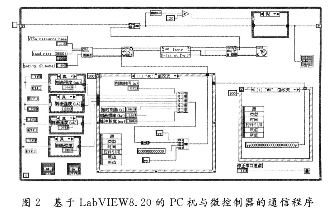
The stimulation parameters are set on the LabVlEW operation interface of the PC in double-precision (DBL) data format. After clicking the "Stimulation" button, the data in these double-precision formats will sequentially create an array containing all the stimulation parameters. The serial port can only read and write strings. Therefore, the array of double-precision data format must be converted to transmit through the serial port. Here, the "array-to-string conversion command" is used to convert the double-precision data array to the corresponding String. In order to prevent errors in data transmission from the computer to the wireless signal transmitting station, the data packet format for serial communication is specified: the length of the stimulus parameter data string is 24, and the first 2 and 24th characters of the data are both "Y". The correctness of the data is judged by the microprocessor of the wireless signal transmitting station, the data is transmitted after the judgment is correct, and the data errors are automatically discarded. From the perspective of safety, the emergency stop function is a must-have for the piggyback micro stimulator. In order to achieve this function, the 23rd command byte is given a definition. If the 23rd byte is "Y", the piggyback micro stimulator is considered to be a stimulus. Command; if it is "O", it is an emergency stop command, the microprocessor of the backpack-type micro stimulator immediately enters the emergency stop state. In the command byte, part of the data is reserved for future expansion of system functions. They have no practical meaning and are transmitted as the character "0". The communication program between PC and microcontroller based on LabVIEw 8.20 is shown in Figure 2.
1.2 Wireless signal transmitter The role of the wireless signal transmitter is to send the stimulation parameters set by the PC to the "knapsack micro stimulator" in the form of wireless signals. It consists of the following parts: a wireless signal transmitter (Transmitter), a step-down voltage regulator circuit composed of AMSlll7-3.3, an Atmega8L microprocessor, a level conversion circuit between a PC serial port and a single-chip serial port. The connection relationship of each part of the circuit of the wireless signal transmitting station is shown in Figure 3. Based on CCllOO wireless transceiver ccllOOA-01 (Liqi International Trade Co., Ltd.) is a low-cost, low-power UHF transceiver, the size of the module is small (20 mm × 30 mm × 6 mm) , Light weight (2.3 g), transmission distance greater than 200 m, mainly working in the ISM and SRD frequency bands.

Since the logic O of the RS 232 serial port is specified to be between 5 and 15 V, the logic 1 is specified to be between 5 and 15 V. The single-chip microcomputer can only receive TTL level (input high level> 2.4 V, input low level <0.8 V, noise tolerance is O.4 V). Therefore, there is no direct communication between the PC and the single-chip computer through the serial port line, and it must go through level conversion. Here, it is made by MAXIM. RS 232 interface chip MAX3232, it uses a single power supply voltage, power supply voltage can work normally in the range of 3.0 ~ 5.5 V. The system uses a 9-pin serial port and completes the communication through 3 lines: RXD, TXD and GND, corresponding to the No. 2 line, No. 3 line and No. 5 line on the 9-pin serial port. In the system design, the chip MAX323 is powered by 5.0 V, and the single-chip is powered by 3.3 V. Therefore, choose the 3.3 V voltage regulator chip AMSlll7-3.3, the entire launch pad can be powered from the PC through the USB interface.
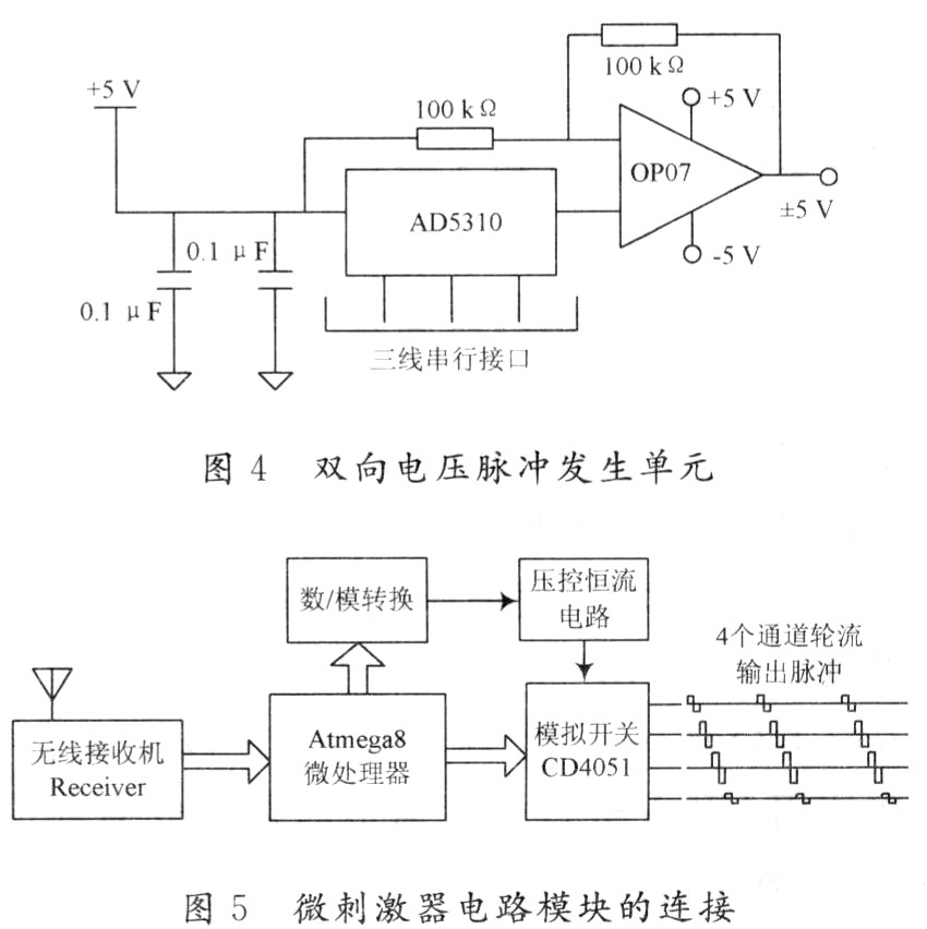
2 The development of the piggyback micro stimulator For the entire system, the animal piggyback micro stimulator occupies the core position, its importance is greater than other parts of the system, and the development is also more difficult. It requires both reliable working performance, low energy consumption and small size. Light weight and long remote control distance. In order to meet the design requirements, the design of the micro stimulator is composed of the following components: Atmega8L microprocessor, wireless signal receiver, D / A conversion chip AD5310 and () P07 operational amplifier composed of two-phase voltage pulse generation unit, bidirectional analog switch CD4051B, voltage-controlled constant current circuit composed of operational amplifier LM358 and resistor, negative pressure circuit composed of TC7660 chip, voltage doubler circuit composed of TC7660 chip, LED working state indication circuit and two rechargeable polymer lithium batteries (4. 1 V, 180 mAh).
The wireless transceiver module CCll00A-01 can send and receive data, and its small size and light weight, therefore, it is also suitable as a micro-stimulator remote control stimulation parameter data receiving module. The single 10-bit serial D / A conversion chip AD5310 and (P07) combine to generate a two-phase voltage pulse signal (as shown in Figure 4). These two-phase voltage signals pass through a voltage-controlled current source circuit (VCcs) composed of LM358 and a resistor Converted to the corresponding two-phase constant current pulse signal. The analog switch cD4051 sends these constant current pulses to the first to fourth stimulation channels in turn under the control of the single-chip microcomputer, so that the required constant current pulse signals are sequentially generated on the four channels (as shown in Figure 5). The device can achieve multi-channel joint stimulation, and each channel is a two-phase pulse with adjustable current intensity. When you need to select any of the four channels for multi-point joint stimulation, set the stimulation intensity of those channels that do not need to be set to 0. In order to improve the ability of the circuit to drive the load, select a 4.1 V polymer lithium battery, double and negative pressure through TC7660, dedicated to the voltage control constant current circuit and analog switch CD4051 for ± 8.2 V power supply; used to generate The operational amplifier () P07 of the two-phase voltage pulse selects ± 4.1 V for power supply; the wireless receiver uses 5 kQ and 41 kQ resistors to divide 4.1 V into approximately 3.6 V for power supply. In the design of the backpack-type micro stimulator, small package surface-mount electronic components (0603 package), and a high-density polymer lithium battery (4.4 g, 180 mAh) are used. Therefore, the overall size of the micro stimulator is greatly reduced. The overall size is about 33 mm × 24 mm × 16 mm, and the mass with battery is about 14.8 g, which is within the weight range of the free movement of the gecko. The circuit design of ultra-low power consumption makes the micro stimulator more than 5 hours when the battery is fully charged. After proper program delay, the knapsack-type micro stimulator can generate bidirectional constant current pulses with a pulse width of 1 ms, a frequency of 50 to 125 Hz, and an intensity of about 0 to 40 μA (at a load resistance of 100 kΩ). Because the system uses mature commercial wireless communication modules, its wireless communication performance is stable, and the remote control distance is about 200 m.
30KW-200KW Brushless Generator
Brushless Ac Generator,200Kw Brushless Generator,30Kw Brushless Generator,Brushless Power Generator 180Kw
Jiangsu Lingyu Generator CO.,LTD , https://www.lygenset.com