
Keywords: coin-operated telephone, CPU control, circuit
1 Introduction Coin-operated telephones have the characteristics of automatic coin collection without special care, and flexible use, which has played an active role in improving labor productivity in the telecommunications service sector and facilitating communication between the general public.
2 Introduction of design functions The main difference between coin-operated telephones and ordinary telephones is the addition of the function of instant timekeeping charging when making calls. Specifically, when the caller puts a specified type of coin into the phone before dialing, and the phone determines that it has reached the specified currency value, the user is allowed to dial. If the dial-up is connected, at the moment when the called party picks up the phone, the exchange will send a charging signal to the coin-operated phone that makes the call. When the coin-operated phone receives this signal, it will receive coin; The caller, the user hangs up, and the coin-operated phone withdraws from the coin. Timing starts when the called phone answers, and a voice warning message will be issued before the call reaches the specified time for the coin. If the specified coin is put again during the alarm period, you can continue to call, otherwise the coin-operated phone will Forcibly remove the thread automatically.
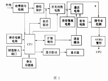
The circuit diagram of the coin-operated telephone set is shown in Figure 1.
3 Circuit composition Each circuit of the coin-operated telephone set is managed and coordinated by the CPU.
It is mainly composed of the following circuits: charge signal detection circuit, polarity protection circuit, coin receiving drive circuit, switch switching circuit, call circuit, voice isolation circuit, number-issuing circuit, 450Hz dial tone detection circuit, single-chip control circuit composed of CPU, The voice module and the display circuit, etc., among which the switch circuit, the currency receiving drive circuit, the voice module and the display circuit, the dial tone detection circuit, etc. are all subject to the monitoring of the control circuit CPU. The input port of the CPU is also connected with a coin detection circuit port, a key input port, and a rate storage port.
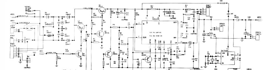
The circuit schematic diagram is shown in Figure 2.
As can be seen from Figure 2, the external line of the phone enters the machine from the PORT4 port, and is added to the positive pole of the polarity change and protection circuit D3 through the phone hook switch PORT6 at the PORT4 (1) pin, and the positive pole of the protection circuit D4 is added to the (2) pin. The polarity conversion circuit is composed of four diodes to form a bridge rectifier circuit. They perform polarity conversion and protection to ensure that other circuits work reliably and stably, and keep the polarity of the signal entering the telephone set consistent.
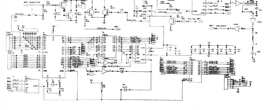
The reverse polarity signal detection circuit connected between the external lines of the telephone is composed of R41, R42 and D5, D6. The function of this circuit is to receive the charging signal (called off-hook signal) sent by the distinguishing switch and send out charging control pulse. China stipulates that the toll signals sent by the exchange are generally two types: one is the reverse polarity signal, which is a DC signal, which is realized by changing the polarity of the coin-line telephone subscriber line feed voltage; the other is the 16KHz pulse The signal is a sine pulse signal with a duration of about 150ms, and the amplitude is required to be about 70mv. The machine uses the reverse polarity signal to make the CPU send the currency receiving drive signal and currency receiving control signal. The circuit takes out the reverse polarity signal from the external line of the phone, and obtains it on the positive pole of D5, D6, and sends it directly to the CPU (12) (13), and then sends the coin collection control signal to the Q9 base through the expansion port of the microcontroller, and sends the coin Detect the signal to the base of Q8.
The coin collection control circuit is composed of Q7, Q8 and part of the resistance, which is controlled by the coin detection signal. The receiving circuit is composed of Q9, Q10 and PORT8 special relays. The function of the money collection circuit is to drive the money collection mechanism to collect coins put into the telephone according to requirements, so that the coins parked in the coin channel enter the coin box. This circuit works in this way. In normal times, because the Q8 base gets a high potential, Q8 and Q7 are turned on, so that a small current flows in the PORT8 coil, and the C36 is charged. Since the local line current is about ten or so mA, the PORT8 relay cannot operate at this time (C36 is a large 1000μF capacitor). When the Q9 base receives the coin receiving signal from the CPU, it immediately turns on, making Q10 turn on. At this time, C36 quickly discharges through the PORT8 relay coil and Q9, Q10. Because the discharge resistance is very small, the PORT8 relay The coil is energized and the relay operates to complete automatic coin insertion. When the coin slides down the coin lane, the PORT8 relay returns to its initial state. C36 charges again.
In addition, when the call time is approaching, the coin-operated phone will automatically start voice prompts. If the caller wants to extend the call time, he will need to put in coins again, and the phone will collect the coin for the second time, because the transfer machine will not be generated at this time Charge control pulse, this machine automatically generates analog currency collection signal through the single-chip microcomputer, so that the currency collection mechanism works to complete the second currency collection. At the same time, the voice prompt is generated by the special language module, and the call circuit is sent to prompt the user.
TEA1110A dedicated telephone integrated circuit is used in the integrated block of the local telephone communication circuit. A chip contains all the circuits and dial interface circuits needed for the call circuit. The conversion between the dial mode and the call mode is completed by an electronic switch. The main functions of the TEA1110A are listed below to facilitate the analysis of the circuit:
IR: input pin of receiver amplifier, SLPE: slope adjustment pin (DC resistance adjustment pin), MUTE: squelch input pin, DTMF: dual-tone multi-frequency signal input pin, REG: regulator decoupling pin, GAR: receiver Amplifier gain adjustment pin, OR: output pin of the receiving amplifier, MIC: (+,-) positive and negative input pins of the sending amplifier, LN: positive line pin.
Here we focus on the functions of the two pins: the first is the MUTE squelch input pin, which is used to control the working state of the call circuit. If the squelch input pin is connected to a high level, the electronic switch of the transmission path connects the DTMF signal to the driving stage of the transmission amplifier, and disconnects the transmission input amplifier and the reception input amplifier at the same time. In the signal state, if it is pulse dialing, no signal is input at the DTMF end, and the entire call circuit is muted. If the squelch pin (M) is at a low level or floating, the electronic switch connects the transmission input amplifier and the reception input amplifier. At this time, the circuit is in a talking state and normal conversation can be conducted. The second is the DTMF dual-tone multi-frequency input pin. During the dual-tone signal sending period, the dual-tone signal is sent from this pin. This pin signal comes from the dialing integrated block HT9200A (7) pin. The LN pin is sent out and sent to the line. Its voltage amplification gain is 26dB. The other channel is sent to the OR pin receiver through the internal attenuator. Because the level of the signal is very low, a slight dial confirmation can be heard in the receiver. sound. In addition, changing the size of R20 can change the gain of the receiver amplifier, thereby changing the volume of the receiver.
The numbering circuit of this machine adopts HT9200A special dialing integrated circuit. The dialing method of coin-operated telephones is the same as that of ordinary telephones, which can be DC pulse or dual tone. The difference is that there are two dialing conditions for coin-operated telephones: one is to pick up the phone, and the other is to put in enough coins. Only after the two conditions are met at the same time, the keys can be effective, and the telephone can send dialing information. The input pin of the HT9200A dial-up integrated block simultaneously inputs the currency detection signal, off-hook signal and the number dialed by the user from the CPU output, and converts it into a dual-tone signal to the outside line.
Each circuit of the coin-operated telephone is controlled and coordinated by a single-chip computer, of which the CPU model is 89C52. Connected to CPUP00 ~ P07 pin is the coin detection circuit port, and connected to CPUP20 ~ P27 pin is the phone key circuit port, CPU can be connected to the corresponding circuit through the input and output expansion port, they are: (1) control language module (U9 AP18108) Generate alarm sound, language prompt sound, various music, etc., output from U9 pin (7) and send it to U6 (IR pin of TEA1110A). Note that when the voice signal is sent from the voice module U9, the receiver amplifier inside the call integrated circuit U6 works, and the receiver connected to the U12 (12) can hear the voice, but we do not want the language signal to be sent to the outside line of the phone, so A voice isolation circuit composed of Q5 and Q6 is connected to the IR pin of the integrated circuit U6. The base of Q6 gets a high level from the output of the CPU, that is, Q6 and Q5 are turned on, which shorts the emitter of Q5 to ground, thus ensuring that the voice signal cannot be sent to the outside. (2) At the same time, the CPU drives the liquid crystal display module to work through the expansion module 74HC244, displays the working status of the coin-operated telephone, and provides an intuitive human-machine interface. (3) The CPU can call all the data in the memory in time through the expansion module. The signal of this memory is U7 XR25165, and it stores the rate information content such as long-distance, agricultural, and local calls for the CPU to call external management at any time.
The coin-operated telephone is also provided with a dial tone detection circuit, which is composed of a dedicated dial tone detection integrated block TA35306P and related components. Its pin (5) is directly connected to the external line end, and it is sent out from pin (4) after detection, and then through the 450Hz dial tone shaping circuit composed of 74LS04, from the output of pin (8) of 74LS04 to CPU (14). Discrimination, it is mainly used to discriminate whether the other party's telephone is off-hook.
4 Practical circuit analysis The external telephone line is connected to the PORT4 telephone line socket, where the anti-lightning protection tube is connected between the socket (1) (2) pins, and the socket (1) pin is connected to the external hook switch of the machine, and the PORT 6 (through the hook switch socket) 1) The feet are sent back to the positive pole of the polarity protection circuit D3, and the telephone socket (2) is connected to the positive pole of the polarity protection circuit D4. When the coin-operated telephone is off-hook, the hook spring (1) (2) is turned on, so that The external line voltage directly passes through the polarity protection circuit, and Q1 of the switching circuit is added to the LN pin of the call circuit U6, thereby forming a call circuit current. The loop current obtains a stable voltage of 12V on D7 and C14 as the working power supply of the CPU, the call circuit and related circuits. Due to the establishment of the current loop, the switch sends a dial tone to the phone. At this time, the dial tone can be heard from the handle, but because no coin is inserted at this time, the phototransistor in the coin detection circuit is turned on, and it is sent to the CPU through the PORT3 port and passes through the CPU. After processing, the control dial integrated block U5 cannot issue a number. When a coin is put in the coin detection circuit, it is sent to the CPU through the PORT3 port and processed by the CPU, the control U5 can prepare to receive keyboard input, because the input terminal of the dialing integrated circuit U5 is directly connected To the output port of the CPU, when the user presses the number on the keyboard, the DTMF pin of U5 controlled by the CPU outputs a dual audio signal to the corresponding pin of the call block U6, and after amplification, the pin LN of U6 Send to outside.
When the called user picks up the phone, the switch sends a reverse polarity signal to the coin phone, and the signal is sent to the local interface through the external line (see Figure 3), which is the reverse polarity composed of D5, D6, R14 and R42 The detection circuit sends the detected signal directly to the CPU (12) (13) pin. When the CPU discriminates that the polarity of the outside signal has changed, the CPU expansion port sends a coin collection control signal to the Q9 base. The coin detection signal is sent to the base of Q8. Only when the above two signals are applied to the base of the corresponding tube at the same time, the money collection mechanism can act to complete the collection task. At this time, the call circuit is connected, and you can make a normal call with the other party.
When the call is close to the specified time, the CPU will drive the U9 of the language module through the expansion module, send a voice signal from its 7th pin to the IR pin of the call integration block U6, and get a voice prompt at the receiver. If the coin is not inserted in time during the specified voice prompt, after a specified time, the CPU sends a hang-up signal to the N2 base through the expansion module U2. When the N2 base receives a positive pulse, N2 turns on and forces Q2 to turn off, making Q1 to turn off. Thereby cutting off the call loop. After a period of alarm, the CPU drives the above circuit to turn over again, so that the main circuit is connected again, but the other party's phone has been disconnected at this time. If you put coins in time during the alarm, send data to the CPU through the PORT3 port of the coin detection circuit, causing the N2 base to take a negative pulse from the CPU, turn off N2, and turn on Q1 and Q2 to ensure that the call loop is connected. At the same time, the CPU controls the voice module U9 to stop the alarm, and controls Q7 and Q8 to receive the coin detection signal and Q9 and Q10 to receive the coin collection signal. Once the above two signals appear at the same time, the second coin collection can be realized.
If the user dials the "11X" number, that is, the special service phone number, such as "119, 110", etc., requires that the coin-operated telephone cannot realize the charging function, then it needs to be judged by the CPU. When the CPU receives "11X" "When the signal is received, the money collection signal it sends will make Q9 and Q10 non-conducting and unable to collect money. At this time, regardless of the polarity of the control signal of the base of Q8, the dialing circuit can send the number normally and the call circuit can Normally make external calls.
2 Li Guangdi. Microcontroller foundation. Beijing: Beijing University of Aeronautics and Astronautics Press, 2001
The Rectifier Bridge is to seal the rectifier in a shell. Divided into full bridge and half bridge. The full bridge seals the four diodes of the connected bridge rectifier circuit. The half bridge is to seal together half of the four diode bridge rectifiers. Two bridges can be used to form a bridge rectifier circuit. One half bridge can also form a full-wave rectifier circuit with a center tap of the transformer. Rectifier circuit and operating voltage.
Rectifier Bridge
Diode Bridge Rectifier,3 Phase Bridge Rectifier,Rectifier Bridge,Rectifier Bridge
Dongguan Agertech Technology Co., Ltd. , https://www.agertechcomponents.com