
This section adds custom user IP (Custom IP) to an existing ARM PS system by using the custom IP wizard (ipwiz) in XPS, understands the basic structure of AXI Lite IP, and masters the customization method of AXI Lite IP for subsequent writing. Complex AXI IP lays the foundation. At the same time, this section of the IP customization method is also applicable to the MicroBlaze processing system.
This section is customized with the IP of a simple LED. There is only one data register. Write a value to it to control the 8 LEDs to turn on and off.
Hardware platform: Digilent ZedBoard
Development environment: Windows XP 32 bit
Software: XPS 14.2 +SDK 14.2
First, create an ARM PS system
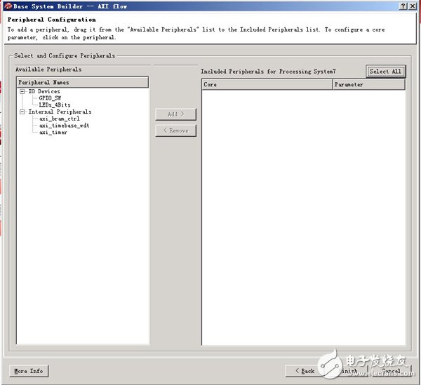
As in the previous sections, first create an ARM PS system using XPS. It should be noted that when selecting peripherals, do not add any peripherals.
Once the ARM PS system is created, you can begin customizing the user-defined IP. XPS provides the Create or Import Peripheral Wizward wizard, making it easy to create custom IPs. Of course, after familiarizing yourself with the AXI IP core structure and code writing rules, you can write your own IP core without using a wizard. This is a wizard.
1, generate AXI IP peripheral template
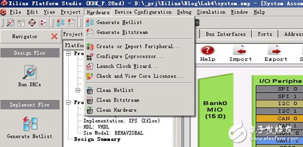
Hardware->Create or Import Peripheral Wizward, start wizard
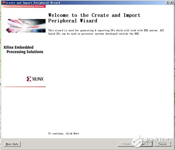
Welcome Screen
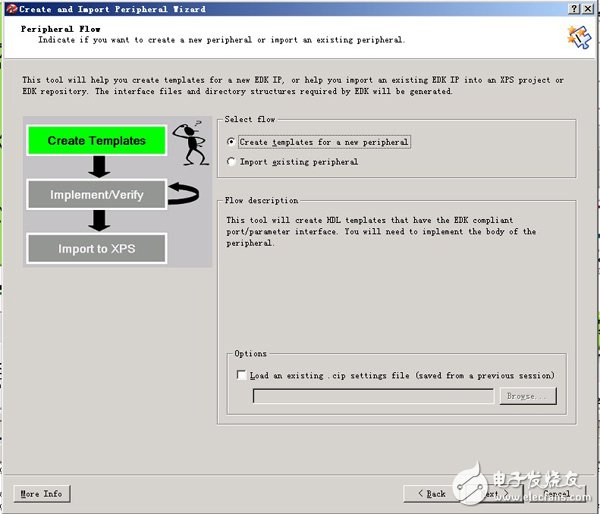
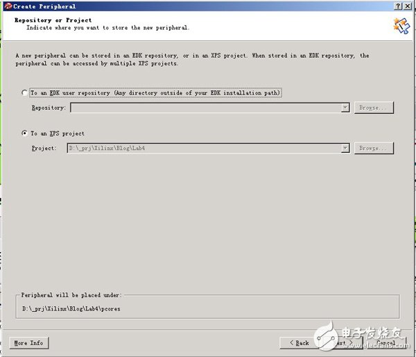
Choose to create a new peripheral from the template
The default is to include the peripherals directly into the current XPS project.
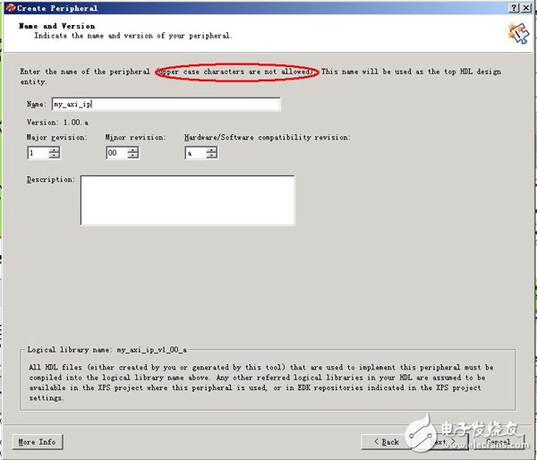
Fill in the name of the peripheral. Note must be in lowercase. Here we are building my_axi_ip. Below is the version control, which can be modified as needed. At the same time, the bottom of the panel also prompts to create a library named my_axi_ip_v1_00_a (actually a directory), and all HDL files that implement this IP are in this library.
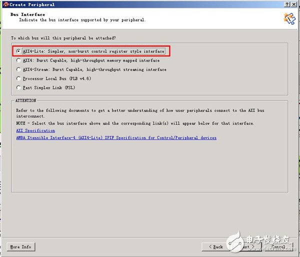
Next, choose the type of peripheral bus. AXI4_Lite is the most basic AXI bus for simple processing. All spatial accesses are accessed by address/register. Burst is not supported. AXI4 is a standard AXI4 bus standard that supports sudden and high speed support. AXI4_Stream is designed for data streams. .
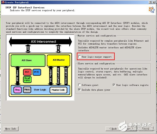
In the IPIF (IP interface) configuration, here are some properties of the interface, such as whether it is an AXI master/slave device. Our custom IP is a slave device and therefore does not require the use of a master device interface.
Select the number of registers you need. Since we only need one data register, here is 1.
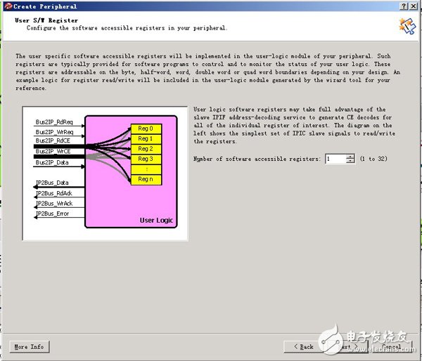
Next is the IPIC (IP Interconnect), which is the interface signal of the IP. Signals beginning with BUS2 mean that these signals are input signals for IP; likewise IP2BUS means output signals.
Here are some signals to make some explanations.
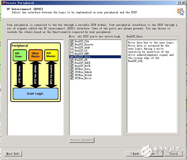
BUS2IP_WrCE (Write Chip Enable, write enable)
AcTIve high chip enable bus to the user logic. These chip enables are asserted only during acTIve write transacTIon requests with the target address space and in conjuncTIon with the corresponding sub-address within the space. Typically used for user logic writable registers selection.
BUS2IP_Data(Write Data, write data)
Write data bus to the user logic. Write data is accepted by the user logic during a write operation by assertion of the write acknowledgement signal and the rising edge of the Bus2IP_Clk.
BUS2IP_BE (Byte Enable, byte enable)
Byte Enable qualifiers for the requested read or write operation to the user logic. A bit in the Bus2IP_BE set to '1' indicates that the associated byte lane contains valid data. For example, if Bus2IP_BE = 0011, this indicates that byte lanes 2 and 3 contain valid data.
IPBUS2_RdAck (Read Acknowledgement, read feedback)
Active high read data qualifier providing the read acknowledgement from the user logic. Read data on the IP2Bus_Data bus is deemed valid at the rising edge of the Bus2IP_Clk and IP2Bus_RdAck asserted high by the user logic.
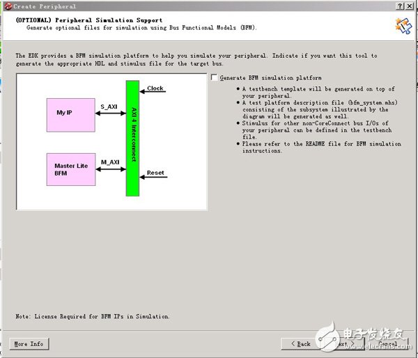
Next, you need to use BFM (Bus Functional Models) to simulate the peripherals. This example IP is very simple, don't use it.
The PLC splitter is used to separate or combine optical signals. A PLC is a micro-optical component based on planar lightwave circuit technology and provides a low-cost light distribution solution with the small form factor and high reliability.
Rackmount Splitter is manufactured using silica glass waveguide circuits that are aligned with a v-groove fiber array chip that uses ribbon fiber. Once everything is aligned and bonded, it is then packaged inside a miniature housing. PLC splitter has high-quality performance, such as low insertion loss, low PDL, high return loss, etc.
Advantages
Suitable for multiple operating wavelengths (1260nm – 1650nm); unstinted.
Equal splitter ratios for all branches.
Compact configuration; smaller size; small occupation space.
Good stability across all ratios.
High quality; low failure rate.


Rackmount Splitter,Fiber Optical Splitter Rackmount,1U Rack Mount PLC Splitter,PLC Fiber Optical Splitter
Sijee Optical Communication Technology Co.,Ltd , https://www.sijee-optical.com