
Among PWMs and electronic ballasts, half-bridge circuits play an important role. The half-bridge circuit consists of two power switching devices that are connected together in a totem pole and output to provide a square wave signal. This article will introduce the working principle of the half-bridge circuit and some problems that should be paid attention to in the half-bridge circuit. I hope to help the power novices understand the half-bridge circuit more quickly.
First let's take a look at the basic topology of the half-bridge circuit.
The capacitors C1 and C2 form a bridge with the switching tubes Q1 and Q2, and the diagonal of the bridge is connected to the primary winding of the transformer T1, so it is called a half bridge converter. If C1=C2 at this time, when a certain switch is turned on, the voltage on the winding is only half of the power supply voltage.
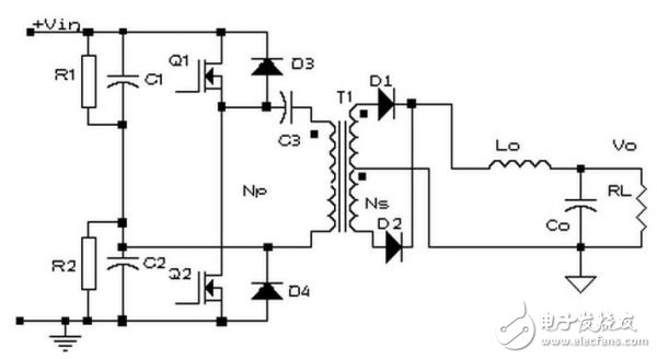
Basic topology circuit diagram of half bridge circuit
The introduction of the concept of half bridge circuit and its working principle
The working process of the circuit is roughly as follows:
Refer to the basic topology circuit diagram of the half-bridge circuit, in which Q1 is turned on and Q2 is turned off. At this time, the voltage applied across the transformer is half of the bus voltage, and the energy is transmitted from the primary side to the secondary side.
Q1 is turned off, and Q2 is turned off. At this time, the two windings of the secondary side of the transformer are in a short-circuit state due to the simultaneous free flow of the two tubes of the rectifier diode, and the primary winding is also equivalent to the short-circuit state.
Q1 is turned off and Q2 is turned on. At this time, the voltage applied across the transformer is also substantially half of the bus voltage, and the energy is transmitted from the primary side to the secondary side. The two diodes on the secondary side complete the commutation.
Some problems that should be paid attention to in the half bridge circuit
Bias problem
Reason: Since the potential of the two capacitor connection points A floats with the Q1 and Q2 conduction conditions, the volt-second value of each transistor switch can be automatically balanced. When the floating does not meet the requirements, it is assumed that Q1 and Q2 are different. The switching characteristic, that is, under the same base pulse width t=t1, Q1 is turned off slowly, and Q2 is turned off faster, then the voltage at point B will be affected, there will be gray area A1, A2 The unbalanced volt-second value is due to the Q1 turn-off delay.
If this unbalanced waveform is used to drive the transformer, a bias phenomenon will occur, causing the core to saturate and generate excessive transistor collector current, thereby reducing the efficiency of the converter and causing the transistor to run out of control or even burn out.
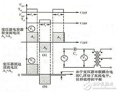
Working waveform of a capacitor connected in series with the primary side of the transformer
Solution: Add a series capacitor C3 to the primary winding of the transformer, and the DC bias proportional to the unbalanced volt-second value will be filtered by the secondary capacitor, so that the voltage will be balanced during the transistor conduction period. Value, to achieve the purpose of eliminating the bias.
Operation principle and attention of half bridge circuit
Two capacitors used as bridge arms:
From the perspective of the half-bridge circuit structure, when selecting two capacitors C1 and C2 on the bridge arm, it is necessary to consider the voltage equalization problem of the capacitor. Try to use the capacitor of C1=C2, then when a certain switch is turned on, the voltage on the winding Only half of the power supply voltage achieves the voltage equalization effect. Under normal circumstances, a resistor (R1 and R2 in the schematic diagram) is connected in parallel at both ends of the two capacitors, and R1=R2 further satisfies the requirement. And power should pay attention to derating. At this time, the functions of capacitors C1 and C2 are used to automatically balance the volt-second value of each switch tube (the difference from C3: C3 is to filter out the DC component that affects the volt-second balance).
Straight through problem:
The so-called straight-through is the phenomenon that Q1 and Q2 are simultaneously turned on at a certain moment, and a short circuit is formed at this time.
solution:
The maximum value of the drive pulse width can be limited so that the conduction angle does not cause a through.
It is also possible to solve the problem topologically, and then use the cross-coupling closed circuit so that when one tube is turned on, the other tube is driven in a closed state until the previous tube is turned off, the sealing is cancelled, and the rear tube is turned on. This automatic blocking has the advantage of automatic adaptation to storage time and parameter distribution, and can be used for full duty cycle.
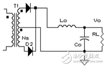
Full-wave circuit
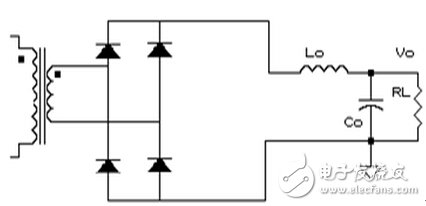
Secondary bridge
The choice of the two circuits is mainly to consider the following two points:
1. Consider the safety of the pipe according to the level of the output voltage;
2, the problem of power loss, mainly the loss of the switch tube and the secondary winding;
Half bridge circuit drive problem:
1, the primary side coil overload limit: to provide independent current limit to the original power tube;
2, soft start: start, limit the pulse width, so that the pulse width slowly rises in the first few cycles of startup;
3, magnetic control: control transistor drive pulse width is equal, to make the forward and reverse magnetic flux equal, no bias;
4, to prevent straight through: to control the upper limit of the duty cycle to reduce;
5, voltage control and isolation: the circuit should be closed-loop control, isolation can be optical isolators, transformers or magnetic amplifiers;
6. Overvoltage protection: usually the switching pulse of the closed converter is used for overvoltage protection;
7. Current limit: The current limit is installed on the input or output circuit and acts when a short circuit occurs;
8, the input voltage is too low protection: the regulation can only be started under a sufficiently high voltage to play good performance;
9, in addition, there must be appropriate auxiliary functions: such as inrush current limiting and output filtering.
Driving characteristics of the half bridge circuit:
1. The upper and lower bridge arms are not common, that is, the switch tubes of the primary circuit are not common.
2. Isolation drive.
This article has summarized and summarized most of the basic knowledge of half-bridge circuits. What is rare is that the problems in the half-bridge circuit are analyzed in detail and the corresponding solutions are given. I hope that everyone can fully grasp this knowledge and lay a solid foundation for their design career.
LED street lights achieve ultra brightness/luminance; energy-saving over 70%. Special modular design for theLens (independent modules) and high luminous efficacy, high CRI, easy for maintenance.Intelligent and isolated power supply (NS semiconductor and Japan Rubycon capacitor), reliable and stable; automatically reduce current against overheating working temperature
Single Arm Led Street Light,Solar Lighting Street,Led Street Light Module
Yangzhou Beyond Solar Energy Co.,Ltd. , https://www.ckbsolar.com