
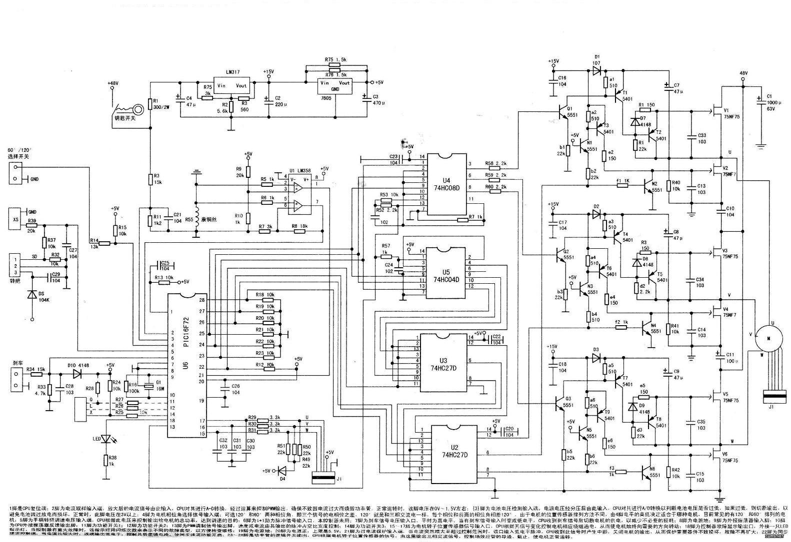
Draw the circuit diagram according to the physical object, as shown in the figure. The controller consists of CPU (PIC16F72), two 74HC27 (3 input NAND gates), one 74HCO4D (inverter), one 74HCO8D (dual input and gate) and one LM358 (dual op amp), 6 It is composed of high-power FET and power up to 350W. It is a typical brushless electric vehicle controller with automatic switching function of 600 and 120° drive modes.
Circuit composition and working principle
The circuit is divided into three parts: power supply circuit, signal input and preprocessing, intelligent signal processing control, and drive control signal power drive switch. The CPU (PIC16F72) microcontroller is the core of the intelligent processing control part. The pin function description of the PIC16F72 can be found in the figure on page 304.
Power supply circuit
The controller has three sets of power supplies. The first group is the battery that provides the total energy. Electrolytic capacitors C1 (1OOOμF/63V), C11 (1OOμF/63V) and C1O (0.1μF/63V) on the board are used to eliminate clutter caused by power lines, circuit board traces, parasitic inductance, etc. interference. Because it is working under high current, high frequency and high temperature conditions, the electrolytic capacitor has the requirements of small loss angle and high temperature resistance, and ordinary electrolytic capacitor is easy to generate heat and burst.
The second group of power supplies provides 15V voltage. The first is to supply power to the FET. Since the FET must have a voltage of 1OV or more and 20V or less to be well turned on, it must have a suitable voltage to supply it, and the 15V voltage is also Pre-regulation is provided for the 5V regulator block. The regulator block is LM317 and the output is 15V. Since the input and output voltage difference of the LM317 cannot exceed 40V, and the input voltage (battery voltage) may be as high as 60V, a 330Ω/2W resistor is added in front of the LM317.
The third group of power supplies is 5V, and the voltage regulator block uses LM78LO5. Since the maximum output current of the 78LO5 is only 100 mA, two 1.5kΩ resistors R75 and R76 are connected in parallel to expand the current. The system has higher requirements for 5V power supply, not only because the power supply voltage of logic circuit, CPU, etc. can not be too high, and since all AD conversion of CPU is based on 5V voltage, if 5V is not allowed, current will appear. Detection, undervoltage detection, and handle control cannot meet the design requirements or even operate. Therefore, the voltage should be strictly controlled at 4.90V to 5.1OV.
2. Signal input and preprocessing circuit
The circuit includes a power supply voltage input, a working current comparison, an amplifying input, a handle turning speed control voltage input, a brake signal input, a Hall signal input of a motor rotor position sensor, and other function switch signal inputs.
(1) Power supply voltage input Since the CPU only receives signals of 0V to 5V, the power supply voltage must be divided into voltages before being input to the CPU.
(2) Working current amplification, input circuit The current signal sampled by the constant copper wire R55 is sent to the non-inverting input terminal (5) of the operational amplifier U1A (LM358) through R6, and amplified, and output to the U6 (CPU) by the (7) pin ( 2) The CPU controls the magnitude of the PWM pulse output according to the level of the signal, thereby controlling the level of the power tube current. The UIB (LM358) acts as a comparator with its output (1) pin connected to the CPU (21) pin. When the current is normal, the U1B (3) pin voltage is higher than the (2) pin, and the (1) pin outputs a high level. When the current suddenly increases to a certain extent for some reason, (2) the foot voltage is higher than the (3) pin, and the (1) pin outputs a low level, thereby pulling the U6 (21) pin overcurrent protection terminal potential low. According to this, the CPU completely shuts off the output of the motor, enters the protection state, and limits the maximum current output by the controller to protect the battery, the controller, the motor, and the like from occurring in a large current exceeding the allowable range, thereby preventing the fault from further expanding.
(3) The handle input part +5V power supply is added to the handle element of the handle turntable, and the handle handle is turned. The control voltage of the 1.2V~4.2V speed generated by the Hall element is divided by R37 and R32, and filtered by C27. Input to the U6 (5) pin, the CPU controls the PWM signal according to this to realize the motor speed regulation.
(4) The brake signal input is divided by R, 34 and R33, and sent to the brake signal (active low) CPU (7). During normal driving, U6 (7) is high level, (13) foot normally outputs driving pulse; when braking, U6 (7) pin level is pulled low, (13) foot stops driving pulse output, reaching brake power off Features.
(5) Motor rotor position sensor input Since the sensor is installed inside the motor, the open circuit output method is adopted. Therefore, in addition to providing +5V power supply, each sensor U, V, W must be connected with pull-up resistors (R49-R51). The signals output by the sensors U, V, and W are filtered by the resistors R29 to R31 and the capacitors C30 to C32, and then sent to the U6 (15) to (17) pins. The CPU energizes the corresponding windings of the motor according to the change of the signal, so that the motor always faces The direction you need to turn. In addition, a diode D4 is connected to the power supply. The grounding is made of a thin copper film as a fuse to prevent the high voltage from coming back after the motor phase line and the Hall signal line are short-circuited, and damage other parts on the board.
(6) Speed ​​limit control When the speed limit switch is turned on, the speed control signal is pulled low by R33, so that the speed cannot be adjusted too high to achieve the speed limit.
(7) Battery undervoltage detection input battery voltage is divided by R3 and R11. After C21 filtering, it is added to U6(3) pin. The CPU judges whether the battery voltage is too low according to this signal. When the battery voltage drops below the controller set value, the CPU stops the output of the PWM chip signal to protect the battery from discharging under low voltage inert conditions and to prevent the battery from being damaged due to overdischarge.
3. Drive control signal and power drive switch
The PWM duty ratio output from the U6 (13) pin drives the control signal, and the output is output through the R53, R52, and C71 carriers (reduced duty ratio), and the phase is unchanged, forming a PWM signal, which is applied to the AND gate U4 (74CO8D) ( 13) The foot is logically combined with the phase switch signal sent from the U6 pin, and then the high level is output from the (3), (6), and (8) pins to the base of the triodes Q1 to Q3 in a certain logic sequence. Turn it on, drive T1, T4, and T7 to turn on, so that the three sets of upper arm field effects V1, V3, and V5 are turned on in a certain logical sequence, and the power supply voltage is applied to the motor winding.
The other way is added to the U5 (74CO4D) (1) pin via R57 and C24, and the PWM signal is formed by inversion, and the (4) pin is output to the NOR gate U3 (74C27D) (2), (4), (10). After comparing with the synchronous freewheeling signal sent by the U6 (22) pin synchronous freewheel control terminal, the (6), (8), and (12) pins are output to the NOR gate U2 (74C27D) (1), (9). ), (10) feet, and the phase switch signals sent from the U6 (26) to (28) feet are combined, and the high level is output by the NOR gates U2 (6), (12), and (8) respectively. To the bases of the transistors N2, N4, and N6, the transistors N2, N4, and N6 are turned on, so that the three sets of lower arm FETs V2, V4, and V6 are turned on in a certain logical sequence, and the current flows through the motor winding. Return to the negative pole of the power supply to obtain an analog three-phase alternating current to rotate the motor.
The status after the self-test is displayed by LED2 and judged. The correspondence between LED display and controller status is as follows:
Flash 1 stop 1--Self-test normally passed; Flash 2 stop 1--Undervoltage: Flash 3 stop 1-LM358 fault; Flash 4 stop 1--Motor Hall signal fault: Flash 5 stop 1-- Down tube fault; Flash 6 stop 1--upper tube fault; flash 7 stop 1--overcurrent protection; flash 8 stop 1--brake protection; flash 9 stop 1--handle ground disconnect; flash 10 stop 1--handle The signal and the hand strap are short-circuited; flash 1 stop 11--the handle signal is not reset at power-on.
When overhauling, first eliminate the short circuit fault, especially the unpowered power tube.
On the side of the electric door lock, the current can be disconnected from the electric door lock connector. If the current is about 65 mA, there is no short circuit in the front stage of the controller.
When there is no short circuit and the motor does not turn, check whether the initial self-test condition is normal.
Check the method of whether the motor Hall element is good or bad: open the electric door lock, and measure the U6 (15) ~ (17) feet with the pointer type multimeter AC 1OV block, that is, the input terminals of the W, V and U phases of the motor Hall. The hand slowly turns the motor wheel. If the pointer of the watch fluctuates around OV~4V, the Hall element of the motor is basically normal.
Check whether the front stage of the controller is normal: First, the controller should be able to self-test to see if the LED2 light flashing is normal. If LED2 flashes once, it means that the self-test passes, otherwise it should check the related fault circuit indicated by the xenon lamp.
After the self-test passes normally, use the multimeter to exchange the 1OV block to measure the U6(26)~(28) foot (ie, the lower tube commutation signal), and turn the turn to make the motor wheel rotate as slowly as possible. If the hand is fluctuating around OV~4V, Then measure U6 (23) ~ (25) feet (that is, the last phase commutation signal), the hands should fluctuate around OV ~ 2V. Then measure the U6 (CPU) (13) pin (ie, the PWM output pin). The voltage at this point changes with the rotation of the handle. If it is OV~4.8V, the output of U6 is basically normal.
The motor current detection and protection circuit consists of current sampling resistors R5, 6, and U1. When the current of the brushless motor increases until the voltage of the U1(2) pin is higher than the (3) pin by about 0.23V, the U1(1) pin goes low, the U6(21) pin goes low, and the MCU enters. Overcurrent protection status.
ZhenHuan Electronic is a leading global supplier of power supplies with all global AC input voltages range from 100VAC to 240VAC single phase. The series 72W to 84W UL Class 2 Power Supply is one wall mount style or desktop stype, all in one stype, high efficiency and reliability class II installations AC to DC power adapter and support class 2, Limited Power Source (LPS) requirements. The series class 2 power transformer offers products output ranging from 4.2 voltage to over 48 voltage, covers a wide variety of AC input blades including America blade, Europe blade, Korea blade, Australia blade, United Kingdom blade and China blade for wall plug adapter; IEC320-C14, IEC320-C8 and IEC320-C6 AC Inlet for desktop adapter.
Variable Power Supply Canada,Variable Voltage Dc Power Supplies,24vdc Power Supplies,48vdc Class 2 Power Supplies,Power Adaptor Dc
Shenzhenshi Zhenhuan Electronic Co Ltd , https://www.szzhpower.com