
This article mainly discusses the principle design and application analysis of the blood glucose meter circuit based on C8051F series single-chip microcomputer, and provides a complete solution for imitation development and debugging production.
Blood glucose measurement usually uses a three-electrode system in electrochemical analysis. Compared with the traditional two-electrode system, the three-electrode system includes working electrode (WE), reference electrode (RE) and counter electrode (CE). The reference electrode is used to set the zero point. The current flows through the working electrode and the counter electrode. The working electrode and the reference electrode form a system that is impassable or basically less energized. The stability of the reference electrode potential is used to measure the electrode potential of the working electrode. The working electrode and the auxiliary electrode form an energized system for measuring the current through the working electrode. A three-electrode measurement system is used to study the relationship between the point of the working electrode and the current. As shown in Figure 1.
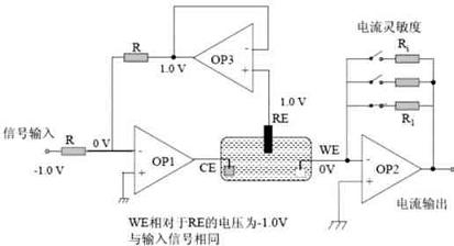
Figure 1 Working principle of three electrodes
Scheme description
The blood glucose meter provides a variety of operating modes to suit the application of different occasions. In addition, it provides free switching and automatic conversion of three common measurement units: mmol / L, mg / dl, and g / l. The conversion relationship between the three units is as follows:
1mmol / L = 18 mg / dL 1mmol / L = 0.18 g / L 1 mg / dL = 0.01 g / L
According to the different requirements of different countries and regions, the blood glucose meter can use any of the above units to display the measurement results, and the conversion method is implemented by using a special code correction bar.
(1) Full use of single chip microcomputer and internal hardware resources. Silicon labs C8051F410 microcontroller integrates a wealth of peripheral analog devices, so that users can make full use of its rich hardware resources. The logic function diagram of C8051F410 one-chip computer is shown as in Fig. 2. The 12-bit A / D converter is used for small-signal measurement. The small-signal current is finally converted into a voltage by the current sampling circuit and sampled by the A / D. Then, the concentration is calculated and displayed on the liquid crystal panel with a predetermined conversion program. The 12-bit D / A converter can output an accurate and stable reference voltage for the three-electrode electrochemical measurement process. Since the D / A output can be arbitrarily changed by program programming, it can be easily changed by changing the D / A value To change the voltage difference between the reference voltage and the working voltage, and can ensure the stability of the pressure difference with 12-bit accuracy, effectively improve the measurement accuracy.
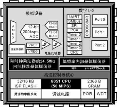
Figure 2 C8051F410 logic function diagram
The temperature sensor is used to collect temperature signals for temperature compensation [4]. Because the blood glucose reagent will have the problem of measurement deviation when the temperature is too high or too low, the ambient temperature is collected by the temperature sensor during the measurement process, and this parameter can be used as temperature compensation outside the temperature range required by the reagent .
The internal 32 / 16kB Flash memory can be used to store measurement data. 2kB of integrated RAM serves as a buffer for measurement data. The blood glucose meter needs to record each measurement data and date in a non-volatile storage medium. Flash memory is usually used, but Flash memory generally has the problem of slow rewriting speed. Therefore, the 2kB RAM is used as a buffer when there is power It is used to record data in the case of, and write the data into Flash every time the blood glucose meter is turned off, indirectly improving the measurement efficiency of the blood glucose meter.
(2) The power supply design uses two ordinary alkaline AAA batteries, and uses the RT9701 and RT9266 to form a high-efficiency boost circuit to boost to 3.3V as the power supply for the entire blood glucose meter. In the power supply circuit structure of the entire instrument, a power switch circuit is designed. When the power is turned off, except for the MCU and the real-time clock can be directly powered by the battery, the power of other circuits is completely cut off, and then the MCU and the real-time clock are put into sleep or power saving state. Can greatly save the standby power consumption and extend the battery life. The wake-up of the MCU is realized by an interrupt. When the switch button is pressed, a key interrupt is generated, thereby awakening the MCU and turning on the power for other circuits, and the blood glucose meter enters the working state again.
(3) Real-time clock design, using s-3530A real-time clock chip [5]. The real-time clock has the characteristics of high precision and low power consumption. The working crystal frequency is 32K, and there is a power saving mode. When the blood glucose meter is not working, it can be put into the power saving mode to save battery power. The I2C bus is used to connect with the single-chip computer, which effectively saves the single-chip I / O line. The leap year is calculated automatically, and the year, month, day and time data are expressed in BCD code format, which provides great convenience for MCU reading and writing.
(4) Design of different user modes. The end customer only needs to carry out blood glucose test and test history, and the debugger needs to know the measured current value to detect the quality of the instrument. Therefore, this solution specifically designs two operation modes to provide end users and debugging during the production process. For personnel use, only a simple and practical special test strip is required to make the instrument count into the super user mode. This mode provides a display interface for testing current. Under this interface, the debugger can test the instrument with standard resistance instead of reagents. Performance. The general end user can only use it in the normal user mode, so that the same procedure can be used for production testing and final sales of the instrument, which brings great convenience to production and maintenance of the product.
(5) Code correction of blood glucose meter. The code calibration is required for the blood glucose meter without replacing a batch of reagents. The so-called code calibration is actually to input a new set of curve fitting parameters to the blood glucose meter. This parameter will be pre-programmed on the code calibration bar. image 3. The characteristic code is actually the integration of the parameters of the fitting curve into a special code form. Figure 4 is the reagent strip, which is prepared by a professional biomedical institution. Because the preparation of each batch of reagent strips cannot be consistent, the parameters of the fitting curve are different each time. This parameter is provided by the institution and the corresponding correction code is burned. The strip is delivered to the end user for use with the reagent. Each time a user purchases a batch of new reagents, he must first modify the parameters of the blood glucose meter through the code calibration bar. The design of the code correction strip uses the same interface as the reagent strip, so it is only necessary to directly insert the detection port of the blood glucose meter like the reagent strip, and the new parameters can be easily input to the blood glucose meter.
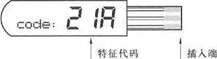
Figure 3 Calibration code bar
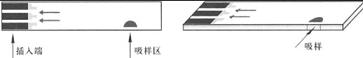
Figure 4 Reagents
(6) Based on the requirements of the previous point, the port of the blood glucose meter must be able to read the reagent strip and the calibration code strip correctly, so the port is a composite port of two functions. Therefore, an ingenious circuit conversion structure is designed on the circuit to automatically determine whether it is a reagent strip or a code correction strip according to the inserted medium and read it correctly.
(7) Design of special code correction bar. Due to the design of the unit automatic conversion, general user mode and super user mode and other functions, these functions are realized by special code correction bars. The principle is to select a few special codes and burn them in the code correction bar. The instrument can automatically read the code correction bar to set the function of the parameter. When reading the code, first determine whether it is a special code. If it is, perform the corresponding operation, otherwise enter the new parameter setting, as shown in Figure 7. Special codes include the following, codes for converting units, codes for switching working modes, codes for clearing memory, etc.
Circuit implementation and human-machine interface
The blood glucose meter circuit structure is shown in Figure 5. The blood glucose meter uses a PDM1621-893 custom LCD module as the man-machine interface. This module can realize various displays such as real-time clock, battery power, measurement unit, alarm signal, code prompt, etc. Programming can provide as many prompt messages as possible in multiple working modes. The structure of the LCD panel is shown in Figure 6. The operation process of the whole blood glucose meter is shown in Figure 7.
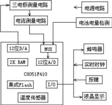
Figure 5 Circuit structure
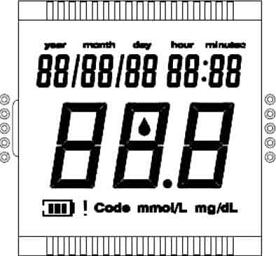
Figure 6 LCD panel structure
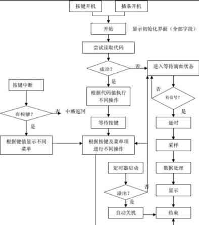
Figure 7 program flow
As a commonly used medical electronic instrument in clinical medicine, the blood glucose meter mainly performs clinical diagnosis by measuring the blood glucose concentration in the blood. Shijixin has many years of service experience in the imitation development, maintenance and repair of various medical electronic instruments and high-end expensive medical equipment. At the same time, we can also provide the extraction and transfer of a full set of technical information for many medical electronic devices such as blood glucose meters according to customer needs, assist product development and application users in maintenance, repair and improvement, or assist engineers in product reference design.
With a constant current of IC, the working voltage of the IC is 12-24V. As long as the voltage is not lower than the rated voltage, the current of each led beacon will be consistent.It is made of high-brightness LED (LED is made of imported chip---high brightness, good electrical).
No pressure drop can be achieved over a specific length and voltage.Suitable for urban lighting projects,home decoration, bars, dance halls, cars, indoor/outdoor advertising and interior and exterior contours of various high-end venues
Constant Current LED Strip,5050 RGB LED Strip,Constant Current LED Strip Flexible,Bright Constant Current LED Strip
SHEN ZHEN SEL LIGHTING CO.,LTD , https://www.sel-lighting.com