
Leading engine circuit diagram
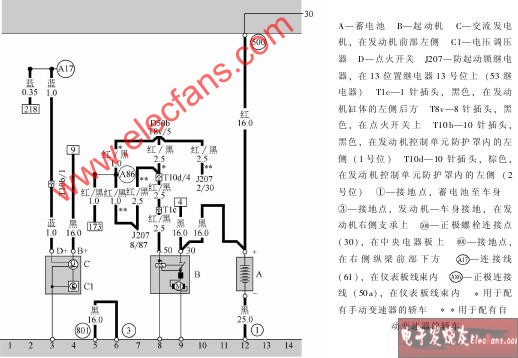
Circuit diagram of battery, alternator, starter, voltage regulator
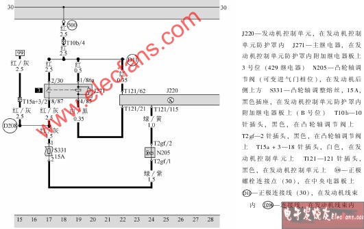
Circuit diagram of engine control unit, main relay and camshaft regulating valve
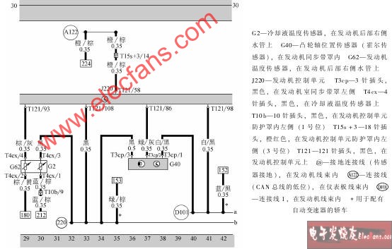
Circuit diagram of engine control unit, coolant temperature sensor, camshaft, position sensor, engine temperature sensor
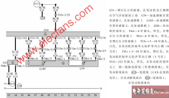
Circuit diagram of engine control unit, boost pressure sensor, accelerator pedal position sensor

Engine control unit, intake air temperature sensor, throttle positioning motor, throttle, angle sensor! Charge pressure limit solenoid valve, charge air recirculation valve, throttle control unit circuit diagram
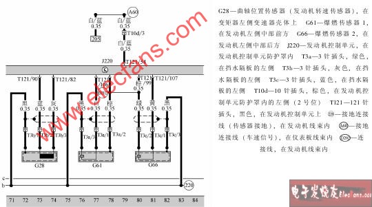
Circuit diagram of engine control unit, knock sensor, crankshaft position sensor
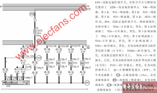
Circuit diagram of engine control unit, nozzle, cruise cruise control switch
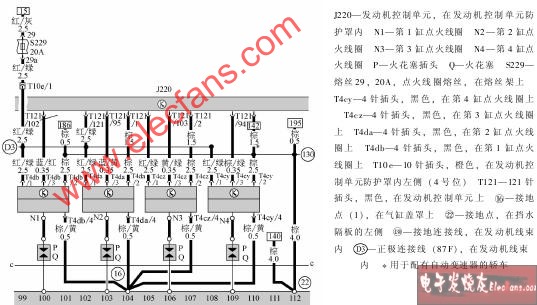
Circuit diagram of engine control unit, ignition coil, spark plug, spark plug connector
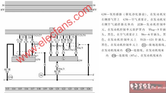
Circuit diagram of engine control unit, air flow meter, oxygen sensor
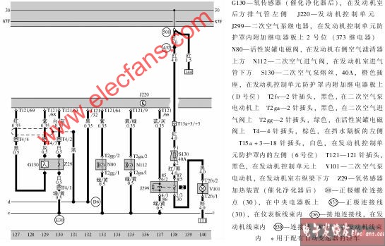
Engine control unit, oxygen sensor, activated carbon tank solenoid valve! Secondary air pump, electric motor, secondary air pump relay, oxygen sensor heating device, secondary air intake valve circuit diagram

Circuit diagram of engine control unit, brake booster relay, brake vacuum pump, brake boost pressure sensor

Circuit diagram of brake light switch, clutch pedal switch, brake pedal switch, engine control unit, multi-function steering wheel control unit
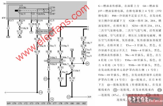
Circuit diagram of fuel gauge sensor, fuel pump relay, fuel pump, and coolant shortage display switch
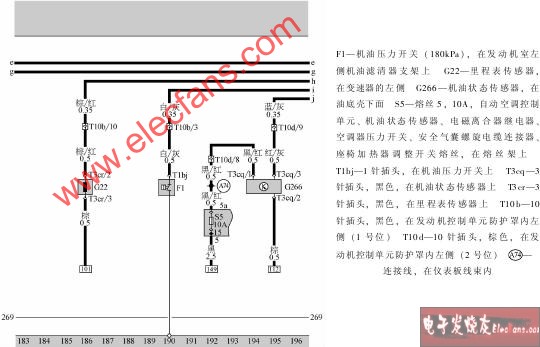
Circuit diagram of oil pressure switch, odometer sensor, oil state sensor
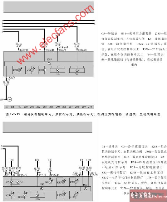
Circuit diagram of combination instrument control unit, oil level indicator, oil pressure indicator, oil pressure alarm, tachometer, odometer
Combination instrument control unit, data bus diagnostic interface, coolant temperature gauge, fuel gauge, coolant temperature, insufficient coolant display indicator, fuel inventory indicator, anti-theft locking system control unit, digital display lighting, electronic throttle control Circuit diagram of fault light, generator charging indicator, cruise control warning light, exhaust warning light
Under the AC system series, we have two different waves system, modifed sine wave and pure sine wave. The pure sine wave AC system is more stable, but the Modified Sine Wave system will has cheaper price and smaller size. Use series connection PWM charge circuit. Charge efficiency is 3%-6% higher than witnout PWM, gives longer life to products.
Solar System,Solar Energy System,AC Gneration System,AC Inverter
Guangzhou City Poojin Electronic Technology Co., Ltd. , https://www.inverter-belttt.com