
We often encounter credit card in our life, such as bus bus card, subway bus card, and when we go out to stay at the hotel, there is also a small room card for card opening. So what is the principle of this card? This is to mention radio frequency identification (RFID) technology.
First, what is radio frequency identification technology
Radio Frequency Identification (Radio Frequency IdenTIficaTIon, RFID) technology is a non-contact automatic identification technology realized by radio frequency communication technology. Compared with traditional touch recognition technology such as barcode and magnetic card, radio frequency identification technology can realize non-visual and multi-target recognition. It has the advantages of waterproof, anti-magnetic, long life, large capacity, no mechanical loss, information can be encrypted, and content can be changed. . Nowadays RFID technology has been widely used in people's daily life, the most common such as public transportation, access control, second-generation ID card, public food and medicine health management. As shown in Figure 1, some of the contactless cards we usually see are often used in RFID technology.
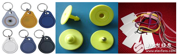
Figure 1 Common contactless cards in life
Second, the principle of RFID card reader
The RFID read/write card operates at a frequency range of 10 to 15 MHz, and the usual operating frequency is 13.56 MHz. The working order of readers and electronic tags usually has two kinds of timings: one is Reader Talk First (RTF): the other is TTF (Tag Talk First). RTF mode: The electronic tag transmits data only when it receives a special command from the reader. TTF mode: The electronic tag enters the energy field of the reader and actively sends its own serial number. The TTF-type radio frequency tag has the characteristics of fast recognition speed and is suitable for applications requiring high speed applications. In addition, the TTF method is more robust in noisy environments and is more practical in situations where the number of tags is dynamically changed, making it more suitable for tracking and tracking applications in industrial environments.
The RFID antenna system includes a reader antenna and a tag antenna. That is, a card reader system has two parts: a contactless radio frequency card (PICC) and a reader (PCD), and the PICC is also called a radio frequency storage transponder. Data exchange between them is done through the ISO/IEC 14443 TYPE A and TYPE B interfaces. The following is a brief description of the working principle of the two.
Third, the working principle of non-contact RF card
The contactless RF card consists of clock extraction, frequency division chain, sequence circuit, Miller code generator, rectifier, modulator, power management, and memory, as shown in Figure 2.
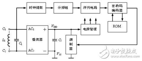
Figure 2: Non-contact RF card internal circuit block diagram
The electronic tag and the reader use inductive coupling for energy transfer and communication. The antenna coil of the reader generates a high-frequency strong electromagnetic field, and the magnetic field passes through the cross section of the coil and the space around the coil, so that the tag antenna close to the antenna coil of the reader generates an induced voltage in the alternating magnetic field. After the rectifier circuit rectifies the coupled RF (13.56MHz) signal and smoothes it through the filter capacitor C2, the power management circuit activates the card circuit when the power supply voltage reaches the internal circuit operating voltage, and the 13.56MHz signal is divided by the frequency division chain circuit. The clock required for communication can be generated. This clock is the baud rate of data transmission. If you want to set the division factor to 128, 256, 1024, 2048, 4096 or 8192, you need to pre-select it. After the information (64 bits) stored in the ROM is read, the Miller code can be generated by the Miller code generator, and the Miller code can be used for load modulation, and the stored information can be sent out.
Third, the working principle of the card reader
The card reader consists of two parts, the transmitting and receiving parts. The working principle of these two parts is briefly described below.
Transmitting: The RF RF signal is output from pins TX1 and TX2 of the PCD base station chip, which can directly drive the antenna coil. The modulation signal and the phase relationship of the RF signal type (modulated or unmodulated carrier) output by TX1 and TX2 can be controlled by the corresponding registers of the PCD base station chip.
Receiving: receiving the modulated carrier signal from the contactless card through the antenna, the carrier demodulation adopts the quadrature demodulation circuit, and the I and Q clocks required for the quadrature demodulation (the difference between the two is 90°) can be in the PCD base station chip produce. After demodulation, the obtained subcarrier modulation signal is subjected to amplification, filtering and other related circuits, and the decision circuit performs subcarrier demodulation, wherein the gain of the amplification circuit can be controlled by the setting of the corresponding register of the PCD base station chip.
Fourth, the interaction process between the card reader and the contactless card
The PCD sends a REQUEST command to all the contactless cards in the range of the antenna field. Through the anti-collision cycle, the serial number of a card is obtained. The card is selected for authentication and authentication, and the memory card is operated after passing, as shown in FIG.
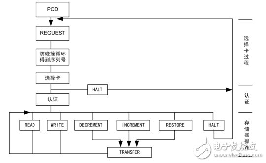
Figure 3 Interaction process between PCD and PICC
The PCD uses a random number, a card serial number, and a key for encryption, and uses a three-time authentication process, as shown in FIG.
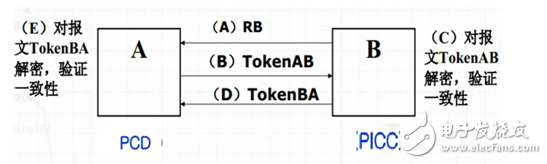
Figure 4 PCD and PICC certification process
A. B sends a random number RB.;
B. A sends TokenAB to B;
After receiving the message TokenAB, C. B decrypts the encrypted part and verifies the correctness of the identifier B and the random number RB, and verifies whether the RB sent to B in A is consistent with the random number contained in TokenAB;
D. B sends TokenBA to A;
After receiving the message TokenBA, E. A decrypts the encrypted part and checks the consistency of the random number.
GreenTouch's industrial for capacitive Touch Monitor has good sealing performance, and has passed EMC anti-interference testing. It has excellent performance such as anti-interference, explosion-proof and anti-vibration, and can meet the requirements of IP65 and IK08 and has good optical stability and touch durability.
GreenTouch's Open Frame Touch Monitor delivers an perfect solution that is cost-effective for worldwide customers requiring a reliable product .Designed with reliability from the start, deliver outstanding image clarity and light transmission with stable, drift-free operation for accurate touch responses.Precise small frame design will be completely sealed Touch Screen, so that it has dust-proof, dirt-proof and water-proof function, and make it easier for customers to install in the cabinet. Designed and built by GreenTouch, the model has a long life cycle period and can supply long-term demands. Even if the future replacement of a new generation of LCD panels, you don't need to do external changes.This model has a global standard of agency certification with GreenTouch warranty and overall after-sale service. The Industrial For Capacitive Touch Monitor open frame touch monitor is a cost-effective touch solution for system integrators and value-added resellers .


Industrial For Capacitive Touch Monitor
Industrial Touch Monitor,Pcap Touchscreen Monitor,Industrial Touch Display,Industrial Touchscreen Monitors,Big Touchscreen Monitor
ShenZhen GreenTouch Technology Co.,Ltd , https://www.bbstouch.com