
1 Introduction
With the development of electronic technology, especially the development of digital technology, it is becoming more and more important to realize the automatic light-off of lamps, save energy and save electricity, and extend the life of lamps with digital circuit technology, and it is close to everyone's actual life. The products of sound and light control circuit have become an indispensable necessity in people's daily life. It does not need a switch. It will automatically light up when someone passes by. It is widely used in public places such as corridors and corridors, and brings great life to people. Great convenience, so it has been widely used. The sound and light control circuit is an electronic switch that operates in the sound and light control circuit. It converts sounds (such as clapping) and light into electrical signals, and amplifies and shapes them to output a switching signal to control the operation of various electrical appliances. It has a wide range of applications in the automatic control of industrial appliances and household appliances.
2 overall circuit design
The whole circuit is composed of a power circuit, an amplifying circuit, a sound control circuit, a light control circuit and a delay circuit.
(1) When the light is bright during the day or night, the entire circuit is controlled by the light control part, and the voice control part does not work. The light control circuit detects the brightness of the outside and outputs a voltage signal corresponding to the degree of brightness, so that the daytime light bulb does not illuminate. At this time, even if there is sound, the light bulb does not light up.
(2) When the light is dark, the on/off of the load circuit is controlled by the voice control part. The voice control circuit mainly converts the sound signal into an electrical signal, and whether the circuit is turned on depends on the strength of the sound signal. When the sound intensity reaches a certain level, the circuit is automatically turned on to light the bulb.
(3) After the lamp is lit, the delay circuit controls the delay for 36 seconds. When the delay time expires, the light is off, and then wait for the next sound signal to trigger.
(4) In addition, the circuit has a strong cut function and is forcibly cut off under special circumstances.
The overall design process is shown in Figure 1.
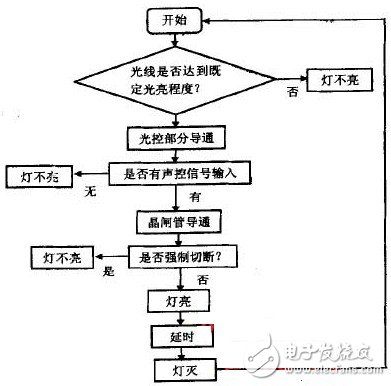
Figure 1 overall design flow chart
3 circuit principle design
The principle block diagram is designed according to the overall design flow chart, as shown in Figure 2.
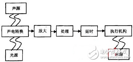
Figure 2 System block diagram
According to the design requirements and principles, the circuit schematic is designed, as shown in Figure 3.
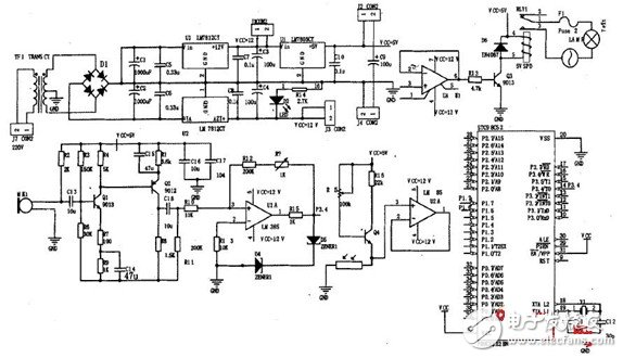
Figure 3 circuit schematic
It can be seen from the figure that the sound and light control energy-saving lamp circuit is composed of a voice control circuit (composed of a sound pickup circuit, an amplification circuit, a hysteresis comparator), a light control circuit (voltage follower), and a single chip control circuit (by a delay circuit and a logic and circuit). It consists of a relay drive circuit and a Power Supply circuit. The voice control circuit and the light control circuit are the core parts of the whole circuit, and the function is to amplify the weak sound signal output by the MIc and convert it into a square wave signal. Finally, the conduction of the relay is controlled by the comparison output of the single chip microcomputer, thereby controlling the lighting of the lamp. Full-wave rectification; Lc, Rc filtering; three-terminal regulator regulator. The specific circuit is suitable according to the requirements of the main circuit and the actuator, and is reliable, inexpensive, and effective. According to the requirements of safety, practicality and low cost, the design structure of the power supply is shown in Figure 4.
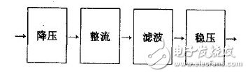
Figure 4 system design structure
4 design and simulation of each component circuit
4.1 Power circuit
The circuit design uses a wide variety of ±12V dual power supply and +5V single power supply circuit, such as transformer buck: bridge rectifier source two-stage circuit. As shown in Figure 5.
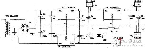
Figure 5 DC Power Supply circuit diagram
1500V DC Power Supply,DC adapter,high voltage power supply
APM Technologies (Dongguan) Co., Ltd , https://www.apmpowersupply.com