
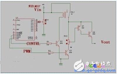
Function: The STC12C2052AD microcontroller successfully implements both ADC conversion and PWM output functionalities.
Application: The system is designed for overvoltage protection using a relay, and it also converts DC voltage into pulsating DC via PWM chopping.
Board Function: The board is used to charge a phone battery.
For the LM317 buck converter, a small current application should be sufficient. Due to time constraints, a switch transistor wasn't purchased, so a 9013 transistor was used instead.
Drawing:
//The following is a working code. If you want to apply this in your own project, simply change the I/O pins and it should work directly.
//Full version of the program download address:
#include //Special header file for STC microcontroller
#include
#define uchar unsigned char
#define uint unsigned int
#define AD_SPEED 0x60 //0110,0000 - 270 clock cycles for conversion
/************ Hebei is waiting for you! &&& less fish welcome you! ******************************/
//
sbit M = P1^5; //Overvoltage indicator
sbit N = P1^3; //Undervoltage indicator
sbit LED = P1^7; //Normal operation LED
sbit CONTRL = P3^4; //Output control
sbit PWM = P3^7;
/************************************************* ***************/
void pwm();
void delayms(uint);
uint ADC();
void InitADC();
void baohu();
float voltage = 0.0;
uint V;
float VCC = 5.05;
uchar mtab[] = {0x01, 0x02, 0x04, 0x08, 0x10, 0x20, 0x40, 0x80};
/***8********************************************* *****************/
void main()
{
CONTRL = 0; //First, turn off the output
delayms(700);
V = 40; //These lines were added when I made a mistake. The purpose was to test what the ADC actually converted.
voltage = 4.0; //Practical testing showed that this replacement value was useless, indicating no ADC.
LED = 0;
CONTRL = 1;
voltage = V * VCC / 256.00 * 5.00;
delayms(1000);
PWM = 1;
CONTRL = 1; //Relay is active, entering protection mode
delayms(1000);
M = 0;
N = 0;
LED = 0;
delayms(2000);
M = 1;
N = 1;
LED = 1;
pwm(); //Generate PWM waveform
delayms(7000);
delayms(100); //Delay
InitADC();
delayms(20);
V = ADC();
baohu();
while (1)
{
V = ADC();
baohu();
delayms(300);
}
}
//
//
void pwm()
{
//PCA module operating in PWM mode
CMOD = 0x04; //Use timer 0 overflow for PCA pulse
CL = 0x00; //PCA timer low 8 bits address: E9H
CH = 0x00; //PCA high 8-bit address F9H
CCON = 0x00;
CCAP0L = 0x60; //Used to control duty cycle in PWM mode
CCAP0H = 0x60; //0xff-0xc0=0x3f 64/256=25% duty cycle (overflow)
CCAPM0 = 0x42; //0100,0010 Set PCA module 0 to PWM mode
// ECOM0=1 enable compare, PWM0=1 enable CEX0 pin as pulse width adjustment output
/*********************
PCA module working mode setting (CCAPMn register n = 0-3 four modes)
7 6 5 4 3 2 1 0
- ECOMn CAPPn CAPNn MATn TOGn PWMn ECCFn
Options: 0x00 no action
0x20 16-bit capture mode, triggered by CEXn rising edge
0x10 16-bit capture mode, triggered by CEXn falling edge
0x30 16-bit capture mode, triggered by CEXn transition
0x48 16-bit software timer
0x4c 16-bit high speed output
0x42 8-bit PWM output
Each PCA module has two registers: CCAPnH and CCAPnL. They are used when capturing or comparing, saving 16-bit count values, used to control duty cycle when operating in PWM mode
*******************************/
TMOD = 0x02;
TH0 = 0x06;
TL0 = 0x06;
CR = 1; //Start PCA Timer
TR0 = 1;
}
//ADC initialization - turn on ADC power supply
void InitADC()
{
P1 = 0xff;
ADC_CONTR |= 0x80;
delayms(80);
//These two registers are used to set the four states of the P1 port, each bit corresponds to a P1 pin, combined operation by state
/*****************
P1M0 and P1M1 register bits 7 6 5 4 3 2 1 0
P1.7 P1.6 P1.5 P1.4 P1.3 P1.2 P1.1 P1.0
The same applies to P3M0 and P3M1. Since the STC12C2052AD only has two P ports, there are only two groups, unlike the STC12C5410AD which has three groups.
P1M0 P1M1 high
0 0 Normal IO port (quasi-bidirectional) P1 register bit 7 6 5 4 3 2 1 0
0 1 Strong push-pull output (20MA current) use P1.7 P1.6 P1.5 P1.4 P1.3 P1.2 P1.1 P1.0
1 0 This mode is available only for input A/D conversion
1 1 Open drain, this mode is available for A/D conversion
For example:
To set P1.2 as an AD input port,
Then P1M0 = 0X02;
P1M1 = 0X02; open drain
When not using AD, it's best to turn off the ADC power and restore to the IO port state.
********************************/
P1M0 = 0x02; //Set P1.1 to open drain state
P1M1 = 0x02;
}
//ADC conversion program
/************************************************* *****
Note: The commands commented in this function are general commands, usable for all AD channels. I have identified one channel on P1.1, so I directly assigned it, saving "flow". The problem that affected me was the while loop in this function.
While (1) //Wait for the end of the A/D conversion
{
If (ADC_CONTR & 0x10) //0001,0000 Test A/D conversion end No
{ break; }
}
This works, but what I originally wrote was:
While (ADC_CONTR & 0x10 == 0);
This can't be written like that. It doesn't work! Because the priority of "==" is higher than "&".
So add brackets: While ((ADC_CONTR & 0x10) == 0);
If you don't often use C language, you won't remember this! ! !
This taught me a lesson. Small issues affect efficiency.
Experience: It's often dead to add a bracket, and it doesn't seem to consume "flow"! !
*********************************************/
uint ADC()
{
ADC_DATA = 0; //Clear result
ADC_CONTR = 0x60; //Set conversion speed 0x60 (fastest)
ADC_CONTR = 0xE0; //1110,0000 Clear ADC_FLAG, ADC_START bit, and lower 3 bits
ADC_CONTR = 0xe1;
//ADC_CONTR |= 0x01; //Select A/D channel P1.1
delayms(1); //Stabilize input voltage
ADC_CONTR = 0xe9;
//ADC_CONTR |= 0x08; //0000,1000 Start A/D conversion
while (1) //Wait for A/D conversion to finish
{
if (ADC_CONTR & 0x10) //Check if A/D conversion is complete
{ break; }
}
ADC_CONTR = 0xe1;
//ADC_CONTR &= 0xE7; //1111,0111 Clear ADC_FLAG, disable A/D conversion
return ADC_DATA; //Return 10-bit A/D conversion result
}
//
void baohu()
{
voltage = V * VCC / 256.00 * 5.00;
if (voltage > 5.25)
{
CONTRL = 1; //Overvoltage protection, turn off the switch tube control
M = 0;
N = 1;
LED = 1;
}
if (voltage < 4.62 && voltage > 4.50)
Heat Shrink,Heat Shrink Sleeve,Shrink Wrap Tubing,Adhesive Lined Heat Shrink Tubing
Dongguan Zhonghe Electronics Co., Ltd. , https://www.zhonghesleeving.com