When we talk about comparators, they are typically constructed using an integrated operational amplifier. Unlike standard operational amplifier circuits, the integrated amplification in comparators operates mainly in an open-loop or positive feedback configuration. As soon as a small signal is applied to both inputs, the op-amp enters the non-linear region, which places it within a portion of the non-linear application range of the integrated op-amp. While analyzing the comparator, the principle of “virtual break†still holds true. However, the concepts of “virtual short†and “virtual ground†are only applicable when assessing the critical situation.
Firstly, there’s the zero-level comparator, also known as the zero-crossing comparator. This voltage comparator is designed to compare and identify an analog input signal, denoted as ui, with a fixed reference voltage UR. If the reference voltage is set to zero, it’s called a zero-level comparator. Depending on the input mode, this type of comparator can be categorized into two types: inverting input and non-inverting input, as depicted in Figures 1(a) and (b).
Figure 1: Zero-crossing comparator
(a) Inverting input; (b) Non-inverting input
Threshold voltage and transmission characteristics are commonly used to describe the operational characteristics of a comparator. The threshold voltage, also known as the threshold level, refers to the input voltage value at which the comparator's output voltage flips, and is simply referred to as the threshold value, represented by the symbol UTH.
The transmission characteristic illustrates the relationship between the output voltage uo of the comparator and the input voltage ui at the coordinate plane. To draw the transmission characteristics, the general approach involves first identifying the threshold values. Then, based on the specific circuit of the voltage comparator, we analyze the input voltage from the lowest to the highest (forward process) and from the highest to the lowest (reverse process). The output voltage changes accordingly, allowing us to plot the transmission characteristics.
Secondly, there’s the any-level comparator, also known as the capture-zero comparator. In this case, the ground terminal of the zero-level comparator is connected to a reference voltage UR (set to a DC voltage). Since the size and polarity of UR can be adjusted, the circuit transforms into an any-level comparator or a capture-zero comparator.
Figure 2: Any-level comparator and transmission characteristics
(a) Any-level comparator; (b) Transmission characteristics
The any-level comparator boasts a simple design and high sensitivity but suffers from poor interference resistance. This means that if the input signal fluctuates due to interference around the threshold, the output voltage might repeatedly switch between high and low levels, potentially leading to malfunction in the output state. To enhance the interference resistance of the voltage comparator, we can consider using a hysteresis voltage comparator with two distinct thresholds.
Thirdly, there’s the hysteresis voltage comparator, also known as the Schmitt trigger. A distinctive feature of this comparator is that it has two thresholds, which are unequal, and its transmission characteristic takes the shape of a "hysteresis" curve. The hysteresis comparator also offers two configurations: inverting input and non-inverting input.
UR is a fixed voltage, and altering the UR value can modify the threshold and the magnitude of the hysteresis. Taking the inverting hysteresis comparator shown in Figure 4(a) as an example, we can calculate the threshold and plot the transmission characteristics.
Figure 4: Hysteresis comparator and its transmission characteristics
(a) Inverting input; (b) Non-inverting input
1. Threshold during the forward process
2. Threshold during the reverse process
The difference between the two thresholds, ΔUTH = UTH1 – UTH2, is referred to as the hysteresis. By examining the above analysis, it’s evident that adjusting the R2 value can influence the magnitude of the hysteresis, while changing UR affects UTH1 and UTH2 but doesn’t alter the hysteresis magnitude. This implies that the transmission characteristics of the hysteresis comparator shift left or right, yet the hysteresis curve width remains unchanged.
Figure 5: Comparator waveform transformation
(a) Input waveform; (b) Output waveform
For instance, the transmission characteristics of the hysteresis comparator and the input voltage waveform, as shown in Figures 6(a) and (b), allow us to draw the output voltage waveform uo, as illustrated in Figure 6(c). From Figure (c), it’s clear that ui changes between UTH1 and UTH2 without causing uo to jump. However, the hysteresis results in an output voltage lag, leading to a level discrimination error.
Figure 6: Strong interference resistance of the hysteresis comparator
(a) Known transmission characteristics; (b) Known ui waveforms;
(c) uo waveform drawn according to transmission characteristics and ui waveform
Fourthly, there’s the window voltage comparator. Both the level comparator and the hysteresis comparator share a common characteristic: when ui changes in one direction (either forward or reverse), uo only jumps once. This enables the detection of only one input signal level. Such a comparator is termed a single-limit comparator.
On the other hand, the double-limit comparator is also known as the window comparator. Its distinguishing feature is that when the input signal undergoes a single-directional change (for instance, ui rises monotonically from a low enough value to a high enough value), the output voltage uo jumps twice. Its transmission characteristics, as shown in Figure 7(b), resemble a window. The window comparator provides two thresholds and two stable output states, enabling the determination of whether ui lies between two specified levels.
Figure 7: Window comparator circuit and transmission characteristics
(a) Window comparator; (b) Transmission characteristics
In conclusion, each type of comparator serves unique purposes and offers distinct advantages, making them suitable for various applications depending on the requirements for sensitivity, threshold precision, and interference resistance.
Voltage Regulator
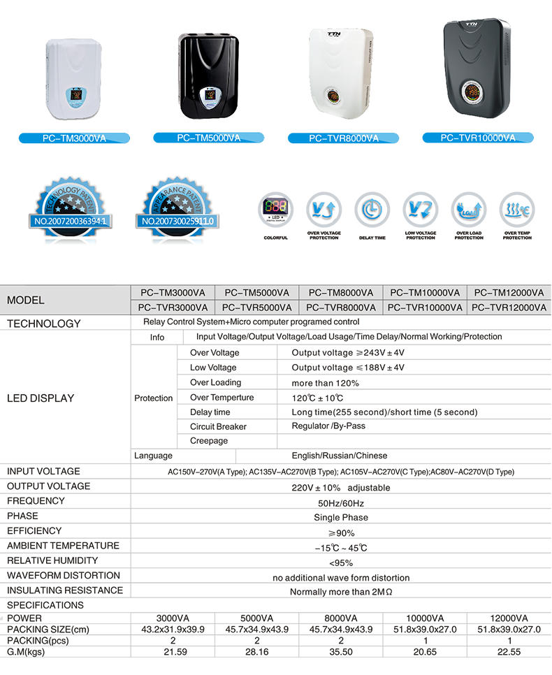
PC-TM series Relay Control Voltage Regulator has the low energy consumption,the over voltage protection,the low voltage protection,the over-current protection,the over-loading protection,the over-temperature protection and so on.It boasts for many kinds of protections,the collection energy conservation and the environmental protection ect.This is a brand-new concept product which possess many new technologies!This series products simultaneously ha applied for many technical monopolies
We already applied many kinds of this products patent, and the technical patent NO: 200720036394.1 and Appearance paten NO: 200730025909.3
2. Use for equipment:
Computer
Test equipment
Light system
Safe alarm system
Ray equipment
Medical equipment
Copy machine
Stereo equipment
Numerical control machine tools
Industrial automation equipment
Color and drying equipment
Test equipment
Hi-Fi equipment


Voltage Regulator,Automatic Voltage Regulator,Alternator Regulator,Voltage Regulation Of Transformer
zhejiang ttn electric co.,ltd , https://www.ttnpower.com


