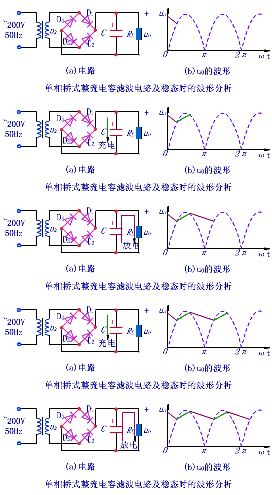
The filter capacitor plays a crucial role in smoothing out the output voltage. Given its large capacity, electrolytic capacitors are typically employed. While wiring, ensure you correctly identify the positive and negative terminals of the electrolytic capacitor. The capacitor filter circuit leverages the charging and discharging capabilities of the capacitor to create a smoother output voltage.
During the positive half-cycle of u2, when its value exceeds the capacitor voltage uC, diodes D1 and D3 turn on, while D2 and D4 turn off. Current flows through the load resistor RL, and the capacitor C gets charged in the opposite direction. Once uC surpasses u2, diodes D1 and D3 are reverse-biased and turn off, causing the capacitor to discharge through the load resistor RL, resulting in a gradual exponential decrease in uC.

In the negative half-cycle, when the amplitude of u2 exceeds uC, diodes D2 and D4 conduct due to the forward voltage, allowing u2 to recharge C, causing uC to rise to the peak of u2 and then begin falling. When uC drops to a certain level, D2 and D4 cut off, causing C to discharge through RL, and uC decreases exponentially. When discharge reaches a specific point, D1 and D3 conduct, restarting the process.
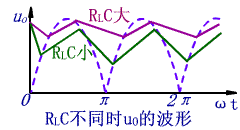
The influence of RL and C on charge and discharge: The charging time constant of the capacitor is rDC. Since the rD of the diode is minimal, the charging time constant is small, leading to a rapid charging speed. The discharge time constant is RLC, as RL is substantial, making the discharge time constant significantly longer than the charging time constant. Thus, the filtering effect relies heavily on the discharge time constant. A larger capacitance C and load resistance RL result in a smoother filtered output voltage with a higher average value.

The primary function of the filter capacitor is to stabilize the output voltage after filtering, converting it into a stable DC voltage. Its working principle involves charging the capacitor when the rectified voltage is higher than the capacitor voltage and discharging the capacitor when the rectified voltage is lower than the capacitor voltage, ensuring basic stability of the output voltage.
Electrolytic capacitors are commonly used due to their large capacity, so be mindful of the positive and negative terminals during wiring. The capacitor filter circuit uses the charging and discharging properties of the capacitor to create a smoother output voltage.
For the positive half-cycle of u2, when u2's value exceeds uC, diodes D1 and D3 turn on, while D2 and D4 turn off. Current flows through the load resistor RL, and the capacitor C charges in the opposite direction. Once uC surpasses u2, D1 and D3 reverse bias and turn off, causing the capacitor to discharge through RL, with uC decreasing gradually in an exponential manner.

During the negative half-cycle, when u2's amplitude exceeds uC, D2 and D4 conduct due to the forward voltage, recharging C and causing uC to rise to the peak of u2 before falling. When uC drops to a certain value, D2 and D4 cut off, causing C to discharge through RL, with uC decreasing exponentially. When discharge reaches a certain point, D1 and D3 conduct, repeating the process.
Influence of RL and C on charge and discharge: The charging time constant is rDC, as the diode's rD is small, making the charging time constant small and the charging speed fast. The discharge time constant is RLC, and since RL is large, the discharge time constant is much larger than the charging time constant. Hence, the filtering effect depends on the discharge time constant. Larger C and RL result in a smoother filtered output voltage with a higher average value.

The rectifying circuit converts AC into DC, but the pulsating component in the DC output is significant. General electronic equipment requires a DC ripple coefficient less than 0.01. Therefore, measures must be taken to minimize the ripple component in the rectified output voltage and preserve the DC component to approximate an ideal DC power supply. This circuit is referred to as the filter circuit in the DC power supply.
Common filter circuits include passive filtering and active filtering. Passive filtering primarily includes capacitive filtering, inductive filtering, and complex filtering (such as inverted L-type, LC filtering, LCÏ€-type filtering, and RCÏ€-type filtering). Active filtering mainly involves active RC filtering, also known as electronic filters.
The pulsation coefficient represents the magnitude of the pulsating component in the DC. The larger the value, the poorer the filtering effect. The pulsation coefficient (S) = maximum AC component of the output voltage / DC component of the output voltage.
The pulsation coefficient of the half-wave rectified output voltage is S=1.57, and the ripple coefficient of the full-wave and bridge rectified output voltage is approximately S=0.67. For full-wave and bridge rectifiers, the C-type filter circuit is used, with a ripple coefficient of S=1/(4(RLC/T)-1), where T is the period of the DC ripple voltage of the rectified output.
The RC-π type filter circuit is essentially a RC filter circuit based on the capacitor filter. As shown in Figure 1, the box indicates the added primary RC filter circuit. If S' is used to denote the pulsation coefficient of the voltage across C1, the pulsation coefficient S=(1/ωC2R')S' at both ends of the output voltage.
From the analysis, the larger the R and C2, the smaller the pulsation coefficient, meaning better filtering. However, increasing R raises the DC voltage drop across the resistor, increasing internal losses in the DC power supply. Increasing C2 increases the capacitor's size and weight, making it impractical. To resolve this, an active filter circuit, or electronic filter, is often used. As shown in Figure 2, this circuit consists of a π-type RC filter circuit made up of C1, R, and C2 and an emitter device comprising an active device—transistor T. From Fig. 2, the current through R is IR = IE / (1 + β) = IRL / (1 + β). The current through resistor R is only 1/(1+β) of the load current. Thus, a larger R can be used, paired with C2 for better filtering, reducing the pulsating component across C2 and stabilizing the output voltage.
Viewed from the RL load resistor, the filter elements R and C2 of the base circuit are folded into the emitter circuit, effectively reducing the voltage by (1+β) times and increasing C2 by (1+β) times. The required capacitance C2 is only 1/β of that needed for a general RCπ-type filter. For example, if the DC amplification factor β=50 of the transistor, a general RCπ-type filter requires a capacitance of 1000 μF. Using an electronic filter, the capacitor only needs 20μF. This allows the use of larger resistors and smaller capacitors for the same filtering effect, making it widely used in small electronic device power supplies.

U-1000 R2V/XV/RV Cable
Standard: NF C 32-321, C32-321/A1 IEC 60502
Rated Voltage: 0.6/1kV
Others: Fire Cable and other property Low Voltage Power Cable can be available
Applications: Those LV Power Cables used for electricity supply in fixed installation, power networks,underground and in cable ducting where where mechanical damages are not to be expected.
N2Xsy R2V Power Cable,12 Kv Cable,Insulated Copper Wire,Enameled Copper Wire
Shenzhen Bendakang Cables Holding Co., Ltd , https://www.bdkcables.com
