
WiMAX technology must be recognized by the market in order to achieve its own advantages in specific application scenarios. This requires application testing to measure system performance parameters. The WiMAX test method is divided into three parts: protocol analysis, radio frequency analysis, and transmission performance analysis. The combined results of the tests were derived from protocol analysis, radio frequency analysis, and transmission performance analysis.
WiMAX receiving test
When testing WiMAX amplifiers and modules, you need to input an ideal test signal. When performing BS (base station), RS (relay station) or SS (terminal) receiver performance test, you need to input a test signal transmitted through the spatial channel.
The digital vector signal source SMU/SMJ/SMATE can generate WiMAX signals that contain complete radio frame settings, MAC (Media Access Layer) settings, channel coding, etc. that conform to specifications or user-defined.
Wireless frame setting
OFDM mode
Figure 1 is a frame structure of an OFDM TDD mode.
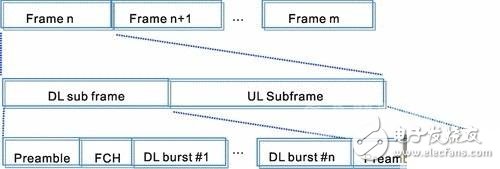
Figure 1 OFDM mode frame mechanism
The downlink subframe consists of three parts: Preamble, FCH (frame control header) and downlink data burst.
The Preamble is located at the beginning of the uplink and downlink subframes and is used for synchronization between transceivers and channel estimation. The symbol structure is divided into a long preamble and a short preamble: a long preamble is used for the downlink subframe, and is composed of two symbols, wherein the first symbol appears once every four subcarriers, and the second symbol appears once every two subcarriers. The short preamble is used for the uplink subframe and consists of one symbol. Each subcarrier occurs once. If the downlink subframe transmits multiple data bursts, the midamble between each burst is also a short preamble.
The FCH (Frame control header) is located after the Long Preamble and consists of a symbol containing system information such as the base station ID and DL data burst for the receiver to demodulate. The DL Burst contains MAC PDUs (Protocol Data Units) and some broadcast information such as DL-MAP, UL-MAP, DCD (Downlink Channel Description), UCD (Upstream Channel Description). A complete PDU shall consist of a 48-bit MAC Header, Payload (data segment) and cyclic redundancy check CRC.
In addition to the Preamble and UL PDUs, the uplink subframe includes a ranging section. The Ranging process is to send a request to the BS by the SS for adjustment of transmit power, delay and frequency offset.
OFDMA mode
2 is a frame structure of an OFDMA mode.
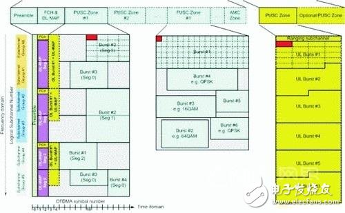
Figure 2 OFDMA mode frame mechanism
Due to the introduction of logical subchannel (logical subchannel) based access, the radio frame structure of OFDMA is more complicated. Figure 2 shows the frame structure plane consisting of symbol number and subchannel number. Preamble, FCH, broadcast information and data burst are all distributed on this plane. This plane consists of Zone and segment, which are distinguished from each other by symbol offset and subchannel offset.
The use of subchannel is divided into PUSC and FUSC, that is, partial use subchannel and all use subchannel, and subchannel is divided into six groups, the number of which is determined by FFT Size, and FFT Size 2048/1024/512/128 corresponds to 60/30/15/ respectively. 3 subchannels.
The RS signal source SMU can currently support automatic generation or custom setting of Preamble, FCH, DL-map, UL-map, ranging, MAC PDU (MAC Header; Payload; CRC). For OFDMA (WiBro) mode, it can support configurations of up to 8 Zones and 3 segments.
Micro motors Based on Dc Motor, Micro Motor belongs to the small size of dc motor,micro motor rotor, back cover, chassis, rotor winding is mainly copper, back cover most of the use of plastic material, motor shell use galvanized steel plate, the micro motor can be ROHS test.
A micro motor is any of a class of rotary electrical machines that converts direct current electrical energy into mechanical energy. The most common types rely on the forces produced by magnetic fields. Nearly all types of micro motors have some internal mechanism, either electromechanical or electronic, to periodically change the direction of current flow in part of the motor.


Micro motor is mainly used in: outdoor lamps, electronic toys, model aircraft, intelligent bin, breeze machine, etc


Method of use: the best stable in horizontal plane, installed on the Micro motor output shaft parts, cannot use a hammer to knock, knock prone to press into the micro motor drive, may cause damage to internal components, and cannot be used in the case of blocked.

Operating temperature range:
Micro motor should be used at a temperature of -10~60℃.
The figures stated in the catalog specifications are based on use at ordinary room temperature catalog specifications re based on use at ordinary room temperature (approximately20~25℃.


If a micro motor is used outside the prescribed temperature range,the grease on the gearhead area will become unable to function normally and the motor will become unable to start.Depending on the temperature conditions ,it may be possible to deal with them by changing the grease of the motor's parts.Please feel free to consult with us about this.
Storage temperature range:
Micro motor should be stored ta a temperature of -15~65℃.
In case of storage outside this range,the grease on the gearhead area will become unable to function normally and the motor will become unable to start.
Service life:
The longevity of micro motor is greatly affected by the load conditions , the mode of operation,the environment of use ,etc.Therefore,it is necessary to check the conditions under which the product will actually be used .The following conditions will have a negative effect on longevity.Please consult with us should any of them apply.
â—Use with a load that exceeds the rated torque
â—Frequent starting
â—Momentary reversals of turning direction
â—Impact loads
â—Long-term continuous operation
â—Forced turning using the output shaft
â—Use in which the permitted overhang load or the permitted thrust load is exceeded
â—A pulse drive ,e.g.,a short break,counter electromotive force,PWM control
â—Use of a voltage that is nonstandard as regards the rated voltage
â—Use outside the prescribed temperature or relative-humidity range,or in a special environment.
â—Please consult with us about these or any other conditions of use that may apply,so that we can be sure that you select the most appropriate model.
when it come to volume production,we're a major player as well .each month,we rurn out 600000 units,all of which are compliant with the rohs directive.Have any questions or special needed, please contact us, we have the engineer group and best sales department to service to you Looking forward to your inquiry. Welcome to our factory.

Micro Motor
Micro Motor,Micro Dc Motor,Micro Vibration Motor,Micro Electrical Motor
Shenzhen Shunchang Motor Co., LTD. , https://www.scgearmotor.com