
LED drive solutions for automotive electronics
As we all know, LEDs are suitable for various automotive lighting components, such as headlights, daytime running lights, fog lights, turn signals, interior lighting, backlighting for infotainment, as well as combined tail lights (RCL) and high-level brake lights (CHMSL).
When establishing an LED-powered electronic drive solution, two main DC / DC power supply categories need to be considered, namely linear regulators and switching regulators. Linear regulators have the advantages of reducing the number of parts and reducing electromagnetic interference (EMI), but have serious drawbacks in terms of efficiency and heat consumption. Therefore, switching regulators are the driving solution of choice for many designers. The DC power supply and the number and type of LEDs required determine the topology selection of the LED driver. If the supply voltage exceeds the total LED voltage, a buck converter is required. If the voltage of the LED group exceeds the supply voltage, a boost converter is required. Finally, depending on the specific conditions, the LED voltage may be higher or lower than the power supply voltage. In this way, power supply topology technologies such as buck / boost or single-ended primary inductance converter (SEPIC) should be used.
When designing a lighting system, in addition to LED power supply, many factors need to be considered. Another major consideration in LED circuit design is thermal management. One way for LED driver integrated circuits to improve thermal performance is by controlling the LED forward current, which is a function of temperature. This can be achieved by using an external current to sense the temperature and control the current supply to the LED, but a more efficient solution is to use integrated circuits with the necessary built-in functions.
National Semiconductor ’s products include numerous switching regulator integrated circuits that can implement a variety of topologies. In addition, National Semiconductor has developed a series of integrated circuits specifically for LED applications, many of which have functions suitable for automotive electronic system applications. This article will discuss several application examples of headlight driving in automotive electronic systems.
Example of a headlight using a boost regulator
LEDs are increasingly used in automotive headlights and other forward-looking lighting systems. A typical headlight application may use 10 white LEDs arranged in various ways. For the case where the maximum VF of each LED is 4V, if the designer wants to use the topology structure where all LEDs are connected in series in one lamp group, a DC / DC stage will need to be set to drive the LEDs. In this case, a single boost switch power stage can be used for the nominal 12V ~ 14VDC power bus.
A variety of integrated circuits developed by National Semiconductor meet this application requirement, such as the LM342x series: LM3421, LM3423, LM3424 and LM3429 components. This series of integrated circuits contains a variety of multi-purpose components that can be used as controllers for low-side external MOSFETs in boost, buck, buck / boost or SEPIC topologies. The LM3421, LM3423, and LM3429 components all use peak current mode controllers and predictive off-time designs to regulate the LED current. The combination of peak current mode controller and predictive off-time design simplifies loop compensation design while providing inherent input voltage feed-forward compensation. The LM3429 is the basic component in the series and is a controller solution with optimized cost and size characteristics. The LM3421 adds an integrated driver for controlling the external dimming FET and the "zero current" shutdown feature of the system. The LM3423 further adds LED status output flags, fault flags, programmable fault timers, and logic pins to control the polarity of the dimming driver. Finally, the LM3424 is similar to the LM3421, but uses a standard peak current mode controller. The LM3424 also has the function of programming the switching frequency or synchronizing the switching frequency with external sources through programmable slope compensation, soft-start and LED current thermal return.
The LM342x series uses controller ICs to achieve the required functionality and maximum flexibility in overall system design. Figure 1 uses the LM3421 as an example to show an example of using the LM342x series to drive an LED lamp group in a boost configuration. A main feature of the LM342x topology is current sensing on the high side of the LED, allowing the cathode of the last LED in the lamp group to be locally grounded at the chassis and allowing the induced voltage to be fed back to the integrated circuit differentially. This is an important advantage, because the LED lamp group and the driver integrated circuit can be separated from each other. 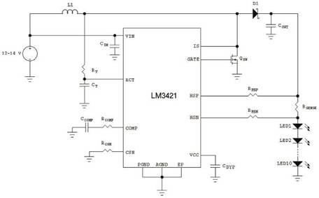
Figure 1 uses the LM3421 boost regulator to drive 10 LEDs
Example of a headlight using a thermal foldback boost regulator
LED manufacturers usually include graphs showing the maximum allowable forward current and temperature of LEDs in data sheets to ensure the reliability of components. This is also called safe operating area (SOA). The maximum current rating of the LED is measured at a lower temperature, but after exceeding a certain temperature, the maximum allowable current value is reduced. Since the primary design element of LED systems is proper heat dissipation and ventilation, many applications need to consider unpredictable conditions, even the best thermal design may not prevent these conditions. For example, the headlight assembly is blocked by sludge or other debris. Because it is critical to the safe operation of the vehicle, under such circumstances, it is necessary to keep the LEDs normally illuminated at a lower operating point while keeping the current in a safe working area to prevent catastrophic failure of the lighting system.
In order to achieve the goal of adjusting the LED current according to temperature, a variety of different methods can be used. One method is to construct a temperature sensing circuit for driving the analog current adjustment pins of the LED driver integrated circuit. A simpler solution is to use an LED driver integrated circuit such as the LM3424 with built-in thermal return (TFB). Figure 2 shows an example of the external components required for the LM3424's hot return function. 
Figure 2LM3424 thermal return circuit
Using the LM3424 to drive LEDs and perform thermal current control has many advantages. First, there is no need to equip most of the complex components (such as multiple operational amplifiers) externally, because these are already integrated in the integrated circuit. In the simplest configuration, only a small number of standard resistors and negative temperature coefficient (NTC) thermistors are needed to achieve thermal foldback. If higher accuracy is required, designers can replace RBIAS and RNTC with precision temperature sensors such as the LM94022. In addition, the LM3424 allows the user to set the temperature at which the LED current begins to thermally return (TBK, set via RREF1,2, RBIAS, and RNTC) and the slope of the current return (set via RGAIN). This allows designers to use a small number of external components to accurately reproduce the current rating decline curve provided in the manufacturer's data sheet, while improving performance with temperature changes, as shown in Figure 3. 
Fig. 3 Example of the curve of rated value drop with temperature
As shown in Figure 2 using the LM3424, the integrated circuit will return the LED current when it reaches a certain temperature. At this time, the LED current is zero. This is different from the LED as the main heat generator in the system. For applications such as headlight components, designers may want to set up a safety function that will always provide light output even if the LED may work beyond the safe working area. For such cases, the LED current versus temperature curve will be as shown in the example in Figure 4. Although the LM3424 does not have this built-in function, it can be easily implemented using an external clamping circuit and prevents the voltage on the TSENSE pin from falling below a predetermined value. 
Fig. 4 Example of the curve of rated value change with temperature (minimum value is non-zero)
Example of a headlight using a SEPIC regulator
Although automotive electrical systems usually operate at 12V to 14VDC, under special circumstances, the supply voltage to system components may exceed or fall below the normal operating value range. For example, in the case of a cold start, the system power supply may be 4.5V or lower, and in the case of a load dump, the voltage may be between 40V and 60V. If LED operation or protection is still required under these special circumstances, the designer may wish to choose a power stage that can provide a constant LED current regardless of the relationship between the power supply voltage and the LED group voltage. A switching regulator using SEPIC can perform boost and buck operations, as shown in Figure 5. 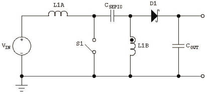
Figure 5 Basic topology of SEPIC converter
SEPIC converters may not be as efficient as buck or boost converters, but the topology has several advantages. In addition to the boost and buck functions, another advantage that is especially suitable for automotive electronic system applications is that CSEPIC capacitors provide isolation between input and output. The disadvantage of the SEPIC converter is that it requires two inductors, but the two inductors can be easily wound on the same core instead of being two separate components. Figure 6 shows an example of an application circuit that also uses the LM3421 controller. 
Figure 6 LM3421 in SEPIC configuration
Combined tail lights using series / parallel LEDs
Another common lighting application is the taillight / flash unit, also known as a combined taillight (RCL). For LEDs with a typical forward voltage (VF) of 3V in a 12V to 14V DC power supply, a possible solution is to use a buck switching regulator. Since the minimum value is 12V, only 3 LEDs are allowed in series. The series / parallel combination shown in Figure 7 can be used because the total voltage of all the necessary LEDs in a series lamp group will exceed 12V. 
Figure 7 Series / Parallel Array
For the dimming and flashing part of this application, a variety of methods can be used to reduce the power provided to the LED array. The most commonly used method is pulse width modulation (PWM) dimming. This method usually uses a special logic signal to turn on and off the LED at high speed to control the overall light output. This method is simple and effective, but it may be rarely used in automotive electronic system applications because an extra line is needed in the wiring harness for dimming signals. Another method is called two-wire dimming, and the power supplied to the LED driver is periodically interrupted to control dimming. The 1.5A integral switching regulator LM3406 has this function, and its true current average value achieves tighter light output control. The integrated N-channel MOSFET does not provide the flexibility that the controller IC has, thus reducing the complexity on the board. Figure 8 shows an application example of the LM3406 using the two-wire dimming method. 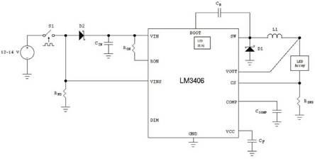
Figure 8 LM3406 configuration with two-wire dimming
The LM3406 includes input voltage sensing pins (VINS) that allow lighting designers to have both fish and bear paws because they can realize the advantages of standard PWM dimming while reducing system wiring complexity (lighting components are far away from the control circuit). The blocking diode D2 allows the input capacitor CIN to remain connected to the LM3406, which is the same as the non-two-wire dimming setting, so that the LM3406 can remain fully powered during the dimming phase. This is more efficient than simply turning components on and off to achieve dimming, because all the internal support circuits of the LM3406 remain energized during the dimming process. Therefore, the component can immediately enter the dimming stage, the integrated circuit has no recovery and operation delay. In this way, in the two-line dimming setting, the LM3406 works in the same way as the logic dimming pin used in output control. The only additional components required for standard PWM settings are the blocking diode D2, the VINS pull-down resistor RPD, and the components used to implement the ideal chopper switch S1.
Example of RCL using a combination of series LED and boost / buck regulator
In an array of parallel lamp groups, configuring LEDs greatly simplifies system design by allowing LED power levels to operate directly from 12V to 14V rails, but parallel / series combinations also have some disadvantages. When looking at the LED manufacturer's data sheet, you can notice two important facts: the light output of the LED is proportional to the current flowing through it, and the dynamic resistance of the LED changes with VF. Manufacturers grade LEDs by VF, luminous flux, and color (or color temperature). For example, a typical VF level may include LEDs ranging from 3.27V to 3.51V (at 25 ° C), and the entire range of all levels may be from 2.8V to 4.2V. Since LED manufacturers usually sell multiple levels of LEDs to customers, it is not practical for cost-conscious designers to rely on all LEDs to have a tight VF distribution.
The following example shows the effect of VF changes. In the experiment, data was collected using the two settings shown in Figure 9. One setting is for 4 LEDs (each LED has a dedicated current source), and the other is for 4 LEDs in parallel (sharing a current source). The data shown in Table 1 is measured within 5 seconds after power-on at 25 ° C to minimize the effect of LED self-heating. 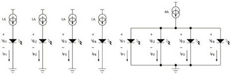
Figure 9 Experimental setup
Table 1 Multi-current source settings (left) and single current source settings (right) data 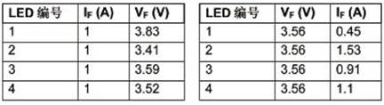
From these data, it can be clearly seen that changes in LEDVF will cause uneven current distribution during parallel operation. Even for graded LEDs, a similar effect can be seen, and the current distribution of each series lamp group in the parallel array is uneven. One way to improve the current distribution among parallel lamp groups is to add ballast resistors to each lamp group. This helps to homogenize the current distribution, but the main problem is the reduced efficiency due to the power consumption of the ballast resistor.
Depending on the specific design, the impact of the above issues may be negligible. However, if the system designer has concerns about the above effects, a single series lamp group can be used as the preferred topology. In this solution, components such as LM3406 can still be used, but will increase the complexity of the system because new front-end components are needed to transmit power voltages in excess of 12V to 14V to power the LED driver. The LED driver then reduces this new voltage to power a single LED light group. This can be easily achieved by adding a boost DC / DC power stage between the DC power supply and the LM3406, as shown in Figure 10. With this topology, all LEDs in the series of lamps have the same current, regardless of the VF value of each LED. 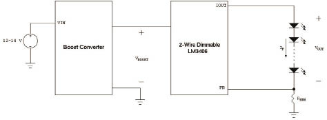
Figure 10 boost and buck combination
Another issue that needs attention is why the step-down power stage should be included instead of directly using the boost regulator to run the LED. The important difference between these two topologies is the output capacitor: the boost regulator requires an output capacitor, while the buck regulator can operate with or without an output capacitor. If an output capacitor is used in the setup, even after the regulator has entered the dimming mode and stops supplying power to the LED, it can still deliver current to the LED for a period of time. Therefore, additional time is required to discharge the output capacitor before the LED output actually stops. The use of series switches in the LED group can still achieve effective dimming, but this requires additional dimming FETs and more complex driver integrated circuits and / or the addition of external components.
In addition to the complexity of dimming, the boost regulator also has other LED driving problems. The boost regulator itself cannot protect the LED from the high line voltage generated during a load dump. In the boost / buck topology, the buck regulator can withstand high voltages without damage or even interrupting normal work. Boost regulators are also susceptible to open circuits (so that the rise of VO is unconstrained) and short circuits (when VO is below VIN, IO loses control). Finally, since the output current is a function of the duty cycle of the boost converter, the inductor current and LED current must be sensed, which also increases the complexity of the driver.
to sum up
This article discusses multiple automotive electronic system application examples and corresponding switching power supply topologies and compatible National Semiconductor integrated circuits. Among them, many LED driver integrated circuits are very suitable for efficient design by automotive electronic system designers.
Automobile device for giving light, especially one that has a covering or is contained within something. Lighting should be provided with good lighting and should minimize glare. For the headlamp, in order to meet the above two requirements, use the two conditions of distant light and near light. The distant light is a long distance light beam that is used in the front of the car or not following other cars. It is generated by the main filament in the focal point of the reflector and the power is large, and the beam direction is approximately horizontal. In order to ensure the safety of driving, the distance of light distance (detection and identification of obstacles) should be greater than the braking distance to realize the timely parking. The speed limit is applied in most countries, given that the required distance light intensity is proportional to the four times of the speed.
Auto Lamp
Auto Lamp,Auto Car Head Lamps,LED Combination Tail Lights,Multifunction Auto Lamps
Heshan Jianhao Lighting Industrial Co., Ltd. , https://www.sunclubtw.com