
Research and Analysis of RFID Middleware Data Filtering Method
RFID is the abbreviation of "radio fequency idenTIficaTIon, radio frequency identification". It is a non-contact automatic identification and data acquisition technology. The technology was first born in 1948. American Harry Strockman published a paper on the theory and The implementation method is described in detail, and it has been 60 years so far. After entering the 1990s, the application scale of RFID technology has expanded dramatically. From 2000 to the present, RFID product types have been greatly enriched, costs have been continuously reduced, and various new applications have emerged.
The RFID system includes two parts: RFID hardware and application support software. The hardware part is composed of electronic tags and readers. Electronic tags are data carriers and are divided into passive radio frequency tags, semi-passive radio frequency tags, and active radio frequency tags. The source electronic tag emits radio frequency energy as a working power source by extracting the reader, and transmits the information in the tag to the reader; the working energy of the semi-passive tag and the active tag is provided by the battery. RFID middleware is the most important part of the RF ID software system.It directly faces the massive data collected by the hardware, filters it, and effectively encapsulates it before submitting it to high-level application software.It is called the RF ID system. Nerve center. At present, the research of RFID middleware mainly focuses on how to filter massive data, de-redundant, and effectively mine useful information. Combining several years of RFID application experience, the author has studied the existing filtering algorithms and proposed an RFID data filtering algorithm with noise suppression function, which mainly solves the noise interference and filtering redundancy in RFID data collection 2 questions about data.
1 Composition of RFID middleware
According to the definition of the RFID authoritative research institution Auto-ID Lab on its EPC IoT Savant middleware, and the EPC application layer event specification and low-level reader interface protocol proposed by EPCglobal, a most basic RF ID middleware should include The following functional modules: Reader interface module, logical drive mapping module, RF ID data filtering module, business rule filtering module, device management and configuration module, upper service interface module, as shown in Figure 1.
The Reader interface is used for data communication between the middleware and the RFID reader. It mainly has two functions of acquiring RF ID data and issuing reader instructions of the device management module.
The device management configuration module is used to adjust the working status of the RF ID reader device, configure the corresponding Reader interface parameters, etc. The logical reader mapping module is used to map multiple physical readers or multiple antennas of the reader into A logical reader. A logical reader represents a specific data collection point (such as shelf 5), regardless of how many readers and antennas the collection point is physically made of. It shields the specific implementation of the data collection point and reduces the software coupling between the upper-layer module such as data filtering and the lower-layer data collection. For the upper layer module, only the logical reader is visible, so the logical reader mapping module has a preliminary filtering function for RFID data.
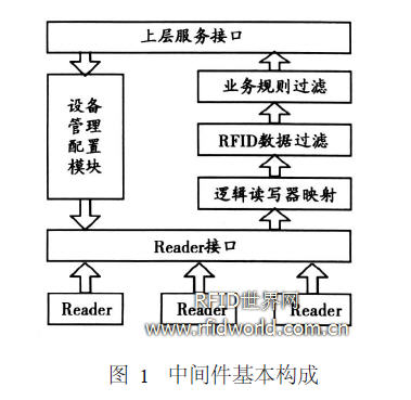
RFID data filtering and business rule filtering, these two parts are collectively referred to as RFID middleware data filtering modules, which filter RFID data at two levels. The former performs de-redundancy and other processing on the massive RFID data reported by the hardware. One of the core functions of recognized RFID middleware. The latter further assembles the filtered RFID data on the basis of specific business rules, making it into event data that meets the requirements of upper-layer software and has commercial meaning, so that the abstract RFID data has a rich practical meaning.
The upper layer service interface sends the filtered and assembled RFID data to the upper layer application software to realize more abundant and realistic functions.
2 Design of RFID data filtering method
2. 1 Existing data filtering methods and problem analysis
The amount of raw RFID data reported from the hardware is huge.Depending on the specific configuration, each reader can report several to tens of tag data per second, but only a small part of them are meaningful to users. Non-repetitive data. If such a large amount of data is uploaded directly without deduplication, it will place a heavy burden on the entire RFID system. Therefore, research on RFID data filtering methods has been a hot spot in recent years.
The existing filtering methods can be divided into the following categories:
1) Establish an event list class. Detect each new tag data, if a new tag is added to the corresponding list, and the tag already exists in the list, only update the status data such as the time of the corresponding tag, not create a new tag Data recording to eliminate duplicate information.
2) Event encoding class. Encode the change of the label state, the label appears to be coded as 0, and the label disappears as 1. The timer mechanism is added to ignore the state transition of the same label within the timer validity time, so as to The status definition and time dimension deduplicate the data.
These algorithms can eliminate redundant data well, reduce the load on the upper-layer system, and have a good filtering effect. But in practical applications, in addition to the de-redundancy of RFID data, there are other requirements for data filtering For example, due to signal instability or other interference factors, the RFID tags of the items on the shelf cannot be detected in every reader / writer cycle; or when the customer pushes the trolley through the shelf, the inside of the trolley The purchased product was misread by the reader in the shelf. In this article, similar invalid RFID data is called RFID noise.
In the design of the above-mentioned types of filtering algorithms, RFID noise is obviously not a factor to be considered. As long as the RFID tag appears, even if it is misread only once, it will be uploaded as an event data. If the upper-layer business rule filtering module does not process these noisy data, it will generate some unexpected event records, which causes a lot of trouble to the data management of the entire system, but the upper-layer business rule filtering module is obviously a piece of noise detection and suppression Difficult thing, because the details of data collection have been completely shielded by the RFID data filtering module, and the most basic basis for the discovery of noise is lost.
2. Design of RFID data filtering method with noise suppression function Design of RFID tag data is reported by the reader at each report cycle. After going through multiple reporting cycles, a typical RFID reader reports data as shown in Figure 2. Show.
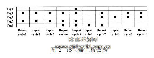
Code the RF ID tags that appear in the reporting period as 1 and the codes that do not appear as 0. For each tag, the event can be recorded as a 01 sequence string. For Figure 2: tag1 can be encoded as 0001111000, which means The tag passes the reader range; tag2 can be encoded as 1111100000, indicating that the tag leaves the range of the reader; tag3 can be encoded as 0000001111, indicating that the tag enters and stays in the reader range. For tag4 and tag5, they appear With noisy data, tag4 should probably not be in the range of the reader, and tag5 did not leave at all. According to the actual situation, RF ID noise can be divided into 2 types: 1 noise and 0 noise.The former indicates that the tags in the non-reader range are occasionally read, such as tag4; ​​the latter indicates that the tags in the reader range are not occasionally detected. I read, such as tag5. According to the traditional filtering algorithm, tag5 will generate a passing event, tag4 will generate 2 leaving events and 2 entering events.
The key to suppressing noise is to identify the occasional noise, so as to erase it through the program. The noise suppression algorithm proposed in this paper adopts the idea of ​​threshold, and assigns a certain weight to each occurrence of the label. , The label that does not appear reduces its weight. When the weight of the label is higher or lower than a certain threshold, the corresponding label event is triggered. The algorithm is specifically described as:
1) Define the weight valueStep that is accumulated after each occurrence of the label.
2) Define the threshold fapp that triggers the occurrence of the tag.
3) Define the threshold fd is that triggers the event of label disappearance.
4) Define the label status field detectS tatus.
5) If the label appears, its weight value plus valueStep.
6) If the label does not appear, its weight is reduced by 1.
7) The weight of the label is greater than or equal to fapp, and detectS tatus = false, then trigger the label occurrence event, and generate a record of the label occurrence. Then set detectS tatus to true.
8) The weight of the label is less than or equal to fdis, and detectS tatus = true, then the label disappear event is triggered, and a record of the label disappears. Then set detectS tatus to false.
In this algorithm, no matter it is 0 noise or 1 noise, because its number of occurrences is very small, its label weight is difficult to be higher than fapp or lower than fdis, and it cannot trigger label events, thereby effectively suppressing noise data. However, no matter how many times the normal tag is reported by the reader, it will only trigger a tag to appear when the weight is greater than or equal to fapp, and the tag status field detect Status ensures that when the tag weight fluctuates above and below the threshold The event will be triggered repeatedly, so this algorithm also effectively solves the problem of tag data redundancy. After processing, the report of the label changed from multiple discrete points to more continuous weight changes, as shown in Figure 3.
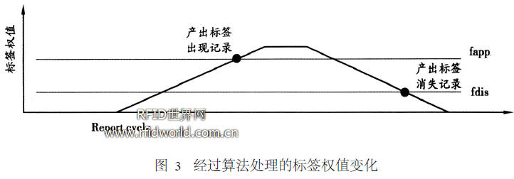
In the algorithm, the greater the ratio fapp / valueS tep between the threshold fapp and the weight value Step, the better the filtering of 1 noise; the lower the disappearance threshold fdis, the more effective the filtering of 0 noise. When fapp / valueS tep is less than or equal to 1, the filtering algorithm will not filter 1 noise, but only retain the function of removing redundant data. Therefore, according to the needs of the objective use environment, the value Step, fapp, fdisp 3 parameters Reasonable adjustment and matching can make the algorithm effectively adapt to the needs of different filtering targets.
3 Algorithm implementation and verification
3. 1 algorithm implementation
The author has implemented the algorithm design idea to verify its adaptability and effectiveness in different application scenarios. The experimental platform uses a single antenna reader with RS232 interface, and the report period of the reader is 1 s, each report The number of tags is 1. The algorithm is implemented in java language, and serial communication is carried out through the comm. Jar development kit.
The first is to build a TagEvent class for tags. The key parameters and methods included in this class are:
public class TagEvent imp lements Runnable {
int value;
boolean detecStauts = false;
int fmax;
int fmin;
public void run () {
while (value> 0) {
try {
Thread. CurrentThread (). Sleep (1000);
} catch (Interrup tedExcep TIon e) {}
if (value> = fmax &&! detecStauts) {
(Trigger label appears record)
detecStauts = true;
}
else if (value <= fmin && detecStauts) {
(Trigger tag disappears recording)
detecStauts = false;
}
value--;
}}
When the main program of the filtering module detects a new tag, it creates an object of the Tag Event class new Tag, assigns initial values ​​to each key field, and starts the timer thread inside the object:
new Thread (newTag). start (); The role of this timer thread is to check the tag weight value every report period and trigger the corresponding operation. After each check, the tag weight value is decremented by 1 to achieve when the tag is not The weight of the report gradually decreases when it is reported. When the value of the weight decreases to 0, the timer thread stops and the object can be destroyed.
When the main module of the filtering algorithm finds that the reported label already exists, it accumulates the value of the label object:
newTag. value + = valueStep;
if (newTag. value> = newTag. fmax) {
newTag. value = newtag. fmax;
}
Among them, valueStep is the cumulative weighted value defined in the algorithm. If the weight value has reached the threshold fm ax, it will be kept at this value to prevent the label weight from being too high after multiple reporting cycles, affecting subsequent judgments.
3. 2 Experimental verification
In the verification process, two application scenarios were simulated: The first is a shelf with a reader. This scenario requires that the shelf reader can stably identify the tagged items that are put in, and will not misreport the goods due to signal fluctuations. Leave the information and maintain a low sensitivity to other items passing through the shelf; the second type is the access control system, which requires immediate response to the tags that appear in the read and write range, but the same tag cannot be reported repeatedly within a certain time .
In the first shelf system scenario, set valueS tep = 3, fapp = 10, fdisp = 0.After the tag enters the range of the reader, the filter module triggers the operation of the tag after about 5 s. Moving out of the reader / writer range for a short period of time, simulating signal interference and fluctuations, and moving another tag from the reader / writer range, the readers did not trigger the appearance and disappearance of redundant tags.
In the second access control system scenario, set valueS tep = 10, fapp = 10, fd isp = 0, when the tag enters the range of the reader, the filter module immediately triggers the operation of the tag, when the tag disappears, within 10 s No longer re-trigger.
4 Conclusion
In this paper, through the analysis of the actual application scenarios of RFID middleware and the research of existing filtering algorithms, we design and implement a RFID data filtering algorithm with a wide range of applications and noise suppression functions. The algorithm was tested. The results show that the algorithm has good noise suppression and de-redundancy capabilities. Under the combination of different parameters, it can adapt to various practical application requirements. The filtering algorithm has laid a good data foundation for the higher-level business rule filtering module. The design and development of RFID middleware has certain practical value.
6000W Three Phase AC Source System
The 3 phase AC Power Supply system model SPS300VAC6000W is featured with high power density, high reliability and high precision, meanwhile it possesses operation interface of touch screen and keys manually. The 3 phase ac power source system is able to analog output normal or abnormal power input for electrical device to meet test requirements, which is applicable to electric, lighting, aviation sectors, etc. It could be applied to enterprise`s production test as well.
Some features as below:
- 5.6`` large touch color screen, possess complete functions and easy to operate.
- Support for USB data import/export and screen snap from front panel.
- AC+DC mixed or independent output mode for voltage DC offset simulation.
- Capable of setting voltage and current output restriction, support for constant current output mode.
- Capable of setting output slope of voltage and frequency.
- Capable of setting ON/OFF phase angle.
- With reverse current protection to avoid current flowing backward.
- Built-in power meter, which is capable of measuring 5 electrical parameters per phase, including voltage, current, power, etc.
- Support mA current measurement function.
5400W Three Phase AC Source System,3 Phase Ac Power Source,3 Phase Power,3 Phase Power Supply
APM Technologies Ltd , https://www.apmpowersupply.com