
Because of the high application flexibility of LED lights, designers can use LED high plasticity to make the vehicle's lighting a highlight of the car's brand when designing the car. Moreover, LED lamps have high luminous efficiency and long service life, which explains from a technical point of view why such light sources are increasingly favored by automobile manufacturers. There are many kinds of lights on the car, and the girders are picked up by the LED light source, including the directional lights, the tail lights, the low beam lights and the brake lights. These LED lights have different roles and different functions, and they also have different power sources for driving them. The requirements, and the topology of the drive circuit must fully meet the requirements of the LED Lamp for the drive power. In addition, the performance of LED lights is constantly evolving. On the one hand, the brightness of the LED lamp with a driving current of only 10mA can be continuously enhanced. On the other hand, the current required by a single LED has reached several amps, which puts different requirements on the control of the LED. There is no, and there is no possibility that a common topology will meet the requirements of all LED sources, and both low cost and high efficiency can be achieved. It is not difficult to understand that the more driver schemes that IC designers may use when selecting and coordinating the driver solution, the more they should pay attention to the matching of the characteristics of each solution and the application requirements.
Basic Data Technically, control circuits designed to control vehicle lighting LEDs take into account many aspects. The design of this circuit has progressed in several different directions: on the one hand, the brightness of LED lamps with a drive current below 50 mA is increasing, and on the other hand, a single LED with a drive current of several amps is obtained. Great development. In this article, we will compare seven topologies that may be used to control vehicle lighting LEDs and explain their performance and their respective application areas. Based on the introduction of various topologies, IC designers can select the one that matches the cost and process requirements among multiple topologies based on the characteristics of the application requirements. However, there is no low-cost, high-efficiency topology in these topologies that is suitable for all application domains.
The LED lamp can only operate normally and reach its maximum service life under the premise of good heat dissipation and stable drive current. In recent years, as OLED (Organic Light Emitting Diode) technology has entered this field, LED lamps are more demanding on the above basic conditions of use, because, compared to earlier, LED technology LED lamps, LED lamps made with OLED technology are more sensitive to high current densities. In addition, the brightness adjustment method adopted in the OLED driving method is an analog driving method, that is, the luminous intensity of the lamp is changed by an analog control circuit instead of a digital pulse width modulation technique (PWM).
Such as high beam and low beam, this high power LED lamp requires almost mandatory clock control power system. Electronically controlled, highly efficient switching converters reduce the power loss that occurs during LED lamp operation. Compared to traditional incandescent lamps, LED lamps and electronic devices are more sensitive to high temperature working environments. Therefore, in designing the converter working environment, in order to ensure efficient operation of the converter, it is necessary to install the converter in a large enough space. That is to say, from the viewpoint of cooling technology, a large enough installation space ensures that the converter can work stably.
Limitations and Requirements The most typical challenge encountered by designers in designing vehicle lighting circuits is to provide a wide range of drive voltages for different types of LED lamps, and the combination of input voltage and input current required by different LED lamps. Different. Normally, the lower limit of the voltage driving to the LED module is about 4V, and the range of voltages that are driven to the LED module is affected by the Start-Stop-System; the electronics behind the polarity protection circuit The lower limit of the drive voltage is usually only 3V. Since the LED lamp output power is set to be constant, this causes the input current to continuously rise when its driving voltage is low.
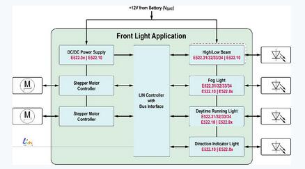
Typical application of headlights
DC/DC power management stepper motor controller high beam / low beam fog lamp daytime running light direction lamp with bus interface LIN controller elmos Semiconductor's E522.xx series controller can meet the front of the vehicle A variety of LED lights required for lighting, and meet the qualifications and requirements set by the solution.
In order to counteract the effect of this current rise, it is often required in the design task book of the LED lamp control circuit to design a suitable circuit device for reducing the input current rating (for example, one can be placed in the lamp, in the lamp When the driving voltage is low, a circuit device that linearly reduces the lamp input current rating can be realized. The analog continuous drive circuit device can continuously supply power to the LED to avoid the occurrence of illumination interruption. The above measures not only solve the problem technically, but also use the above measures to reduce the cost of the solution when designing the maximum current of the polarity protection circuit and the maximum current of the EMC (electromagnetic compatibility) filter element.
In general, if the operating voltage of the LEDs connected in series is greater than or equal to 2V, or even when the required voltage reaches 55V or more, driving with an integrated circuit (IC) driving scheme cannot generate sufficient driving current. In addition, driving the series LEDs above, the current in the circuit can be adjusted to achieve a current range that satisfies the condition that the ratio between the maximum current achieved by analog adjustment and the minimum current achieved by analog adjustment is greater than 10. :1. In general, the adjusted current has an extreme value of 1.5A. In the experimental study, the extreme value of the analog output current has reached a range greater than 3A and less than 6A. At this time, a single diode for realizing the point source. The luminous flux is greater than 1000 lumens.
The question now is which topology matches which LED? The following examples show some of the topologies for specific application areas, where the cost of implementation is appropriate, and the potential areas of application for these topologies. The starting point for choosing these examples is to reflect the desire of the application developer to create a topology that is a specific combination, that is, a combination of constant current and voltage obtained on the lighting device. There are many ways to design such a topology.
Linear topology power integrated circuit converters are suitable for LED lights with low current and power, such as turn signals, tail lights, fog lights, and low-cost daytime running lights. The total cost of these power ICs is relatively small, and typical power integration is very simple to apply. In principle, the amount of external radiation during the operation of the power supply IC is small, so it is almost unnecessary to equip the power supply integrated circuit with an EMC (electromagnetic compatibility) filter. This article does not discuss the issues associated with inductive memories required for switching solutions.
When choosing a drive scheme that drives the LEDs, which solution is often limited by the size of the current in the drive, in addition to being limited by the LED circuitry. Linear actuators commonly used in vehicles typically have current limits greater than 40 mA and less than 70 mA. The circuit designer must take action on this constraint to ensure that the temperature of the driver module does not rise above the limit to ensure safe operation of the circuit. A temperature management scheme has been developed in the industry to ensure that the current limit in the drive can be greater than 150 mA. Elmos Semiconductor's E522.80/81/82/83 LED controller is a good example of a viable temperature management solution with three independent current sources built in the series. Down, the total current driven to the LED can reach 450mA.
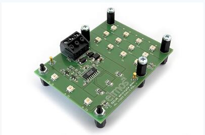
E522.81 Linear Crossflow LED Evaluation Board
For example, the E522.80/81/82/83 series linear controller can be used as a power supply integrated circuit controller to control LED lights such as turn signals, tail lights, etc. with relatively low operating current and power, that is, operating current is greater than 40 mA and less than 70 mA. LED lights within this range.
In addition, Elmos Semiconductor supports multiple chip cascades for troubleshooting when any string of lamps fails. Different processing objectives and industry rules have been set for handling individual LED faults in different countries, including provisions for fault tolerances and regulations and processing targets for incomplete light sources to completely stop working. If a local controller is provided, the PWM signal can accurately identify possible hardware defects and send the identified information back to the controller.
Boost-to- GND-Topology The Boost-to-GND topology is a typical topology and is also known as a boost or Step-Up boost converter. It is a very efficient and generally EMC (electromagnetic compatibility) very friendly topology. However, this topology can only be used when the load voltage is greater than the input voltage under all operating conditions. Therefore, this topology is hardly used in vehicle lighting circuits. Because the inductive memory is placed at the drive in this topology, the input current of the Boost boost converter remains approximately constant, so this topology is more easily filtered than other topologies. When the load of this topology is within the load range that it can use, and considering the Jumpstart requirement (the drive voltage is not higher than 28V for a long period of time), the voltage of the circuit is greater than 30V. And within the interval of less than 60V. Since the LED lamp requires very high temperature conditions, it is technically impossible to use the Boost topology in the circuit of the LED lamp in the above voltage range.
Last but not least, if the output voltage exceeds 60V, special measures must be taken to ensure that personnel are not electrically injured when touching the relevant electronics. The role of the Boost converter once again plays a more important role when it comes to OLED stacks with larger forward voltages. For example, elmosE522.31/32/33/34 is the solution for Boost converters used as LED controls.
Boost-to-Battery-Topology The basic principle of this topology is similar to the basic principle of a typical Booster topology, in which the base point of the LED load is not ground but the drive voltage. The Boost-to-Battery topology can also be referred to simply as a Boost-to-Bat-topology. Any input voltage of this specification can output an output voltage of any specification after passing through this topology. Therefore, from a technical point of view, it is a Buck-Boost topology.

The Boost-to-Battery topology can also be abbreviated as Boost-to-Bat-topology. Any input voltage can output any specification output voltage after passing through this topology; however, it must be configured in this topology. A differential current sense amplifier.
The lowside switch loads the current in the first phase into the inductor. In the second phase (ie, the state where Lowside has been disconnected), the energy stored in the circuit is passed back to the output through the freewheeling diode.
The use of this topology must meet the premise that a differential current sense amplifier is placed in the topology, and the differential current sense amplifier can achieve accurate measurements over a wide common-mode voltage range. Elmos's LED driver E522.31/32/33/34 includes a special amplifier that can measure from >4V to less than 55V. The measured offset voltage is less than 3mV and the measured temperature range is less than 150°. C. In addition, the above driver can also provide external frequency synchronization and an optional internal frequency spread modulation. If a high EMC (electromagnetic compatibility) requirement is imposed on the LED control device, the driver can help the whole The system meets the requirements for automotive electronic components in CISPR25.
Different diagnostic functions are provided in the internal and external circuits of the above driver electronics. The driver can work normally when the voltage is below 60V, and the digital and analog dimming functions can be realized by the driver. Automotive internal voltage regulators (LDOs) can simultaneously supply 3.3V and 5V to controllers or analog auxiliary circuits.
Buck-to-Ground topology The second classic topology is the Buck-to-Ground topology, referred to as the Buck-to-GND-topology. This topology is a step-down converter (Step-Down-Converter or Buck-Converter). The converter allows the load voltage to be less than the input voltage, and this performance makes sense for solving electronic control problems. In general, such converters can provide large currents for one to two LED lamps. In contrast to the Boost topology, the buck converter on the drive side can regulate the current and the load current is set to the upper limit. Therefore, converters with this topology do not always require a circuit arrangement that reduces the input current rating, as with a Boost topology.
The buck converter works with daytime running lights (DRL), fog lights, turn signals, lights, and backup lights. A number of lighting products have been developed on the market, for example, an elmos E522.10 controller based on a buck converter has been developed for lighting products with a current of less than 2A. For LEDs with large currents, ie, less than 6A, a solution based on switching regulator ICs has been developed on the market. This solution allows flexible selection of the on-resistance in the external driver transistor. This means that designers can reduce costs based on actual conditions. Buck-to-Battery topologies can be used in some cases, such as E522.31/32/33/34 with LED controller.
The Buck-to-Battery-topology also has a topology that uses N-type transistors for use in the Lowside controller, which is used to drive LED lights (known as the Buck-to-Battery topology or Referred to as the Buck-to-Bat topology. During the operation of this controller, the LED load is negatively charged relative to the battery, so the potential of the LED is always between the battery drive potential and the ground potential. During the alternating charge discharge of the inductor through a Lowside switch or a free-wheeling diode, a small current from the inductor that supplies a small amount of power supplies power to the series connected LED lamps.
The Buck-to-Battery topology helps reduce switching losses in the sides and reduce the amount of outward radiation through the high switching level through the small voltage amplitude at the power switch.
With a small voltage amplitude at the power switch, this topology can help reduce edge switching losses and reduce the amount of outward radiation through the high switching level. Because this topology can always be matched to a given current condition and voltage condition by an external switch, such a solution is quite flexible. In the component design process, the topology design developer must always pay attention to the maximum duty cycle (Duty Cycle) determined by the converter. Elmos recommends balancing this Buck-to-Battery-topology with a classic Buck topology. At this point, in most cases the converter allows a 100% duty cycle (Duty Cycle), and after the classic Buck topology is balanced, the input voltage range available for the Buck-to-Battery-topology can be extended downward. Because Buck-to-Battery- also requires a differential amplifier, elmos supports a variety of ways to support developers, such as elmos provide a complete, complete demonstration circuit.
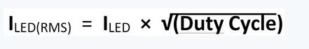
The effective value of the circuit used to buffer the supply voltage in the capacitor is a requirement that is often underestimated. When it comes to Buck-to-Battery (and Buck-to-Battery), the current tends to be trapezoidal or rectangular. In the example where the duty cycle of the Buck-converter is 50%, the effective RMS-current is half of the output side load current.
In some cases, an LED converter E522.32/34 with two integrated control circuits can solve the effective current problem; the above converter can also be used in a multi-phase system. That is, by deflecting the phase in the power supply circuit by 180° and shunting the current, power consumption in different components can be significantly reduced.
Sepic-Topology In principle, the Sepic topology requires a lowside-switched converter, such as the E522.31/32/33/34 of the LED controller family, which can be applied to the Sepic topology. Not only the input voltage, but also the output voltage can be derived from the voltage requirements of the transistors and diodes used in the Sepic topology (generally, the voltage requirements and input voltage and output voltage of the transistors and diodes used in the Sepic topology) And related). Therefore, it is recommended to use an external power switch. In the market, you can buy a variety of high-quality models and external power switches. When you choose, you can flexibly choose different power supply external power switches, or you can flexibly choose external power switches with different working currents. High RMS current requirements play an important role in the choice of coupling capacitor size. Therefore, ceramic coupling capacitors are commonly used as coupling capacitors in external power switches.
One of the problems often encountered when designing a work involving a Sepic-topology is whether a coupling consisting of two coils is required. If you consider this problem from the working principle, the answer is not needed, but if the core is provided with a coupling consisting of two coils, it can be said that the coupling limits the current rise in the two coils. In summary, it can be concluded that a mutually coupled coil inductance value is only half of two separate inductor coils. In general, in summary, a coupled coil is a reasonable option regardless of the compactness or cost of the device. From the perspective of control technology, coupling also has its advantages, because coupling reduces the complexity of the associated magnetic pole.
Zeta, a converter that has not yet been understood In principle, the Zeta converter is a Sepic converter with a head rotated. In contrast to the Sepic converter, the Zeta converter is used as a Highside switch. A network that can be compared to the Sepic topology transmits energy to the output. The advantage of this topology is that it has a low electrical strength, which is a necessary condition for the normal operation of the coupling capacitance between the coils. In addition, there are other principles similar to the Sepic topology, and the coupling between the two inductive memories is also applicable to the Zeta converter.
In general, Buck converter integrated circuits are suitable for operation in a Zeta topology. The power switch must be able to withstand the negative drain voltage of the output voltage relative to the converter ground potential voltage. For the above reasons, it is not advisable to use an asynchronous excitation stage in this topology; in fact, it is necessary to use a driver with an external P-FET or a drain integrated terminal with a free connection. Here, controllers E522.01-09 and E522.10 from Elmos can be used.
The performance of the Zeta topology in EMC (electromagnetic compatibility) is similar to that of the Buck converter. Discontinuous input current and continuous output current will occur. The Zeta topology is an interesting option if it is a power source that needs to be driven to a small load and cold-cranking appliance. The above application requirements can be achieved by designing and developing on the basis of the converter E522.10 or on the basis of the controller series E522.01-09. This Buck converter with built-in driver and leakage voltage withstand voltage less than -10V is also particularly suitable for Zeta topology.
Steel poles are commonly used to carry several types of electric power lines, distribution lines and lighting system. Distribution lines carry power from local substations to customers. They generally carry voltages from 4.6 to 33kV for distances up to 30 miles, and include transformers to step the voltage down from the primary voltage to the lower secondary voltage used by the customer. A service drop carries this lower voltage to the customer's premises.
Telecommunication Mast, Telecommunication Antenna Mast,Telescopic Telecommunication Mast,Signal Telecommunication Mast
Yixing Steel Pole International Trading Co., Ltd , https://www.yx-steelpole.com