
Peng Li, Guangzhou Research Institute of China Telecom Co., Ltd.
Keywords: NFV IMS SDN
1 Introduction
NFV (Network Functions Virtualisation) changes the way existing network operators construct networks: Instead of using dedicated network equipment, IT virtualization technology is used to deliver standard high-performance servers, switches, and storage devices. Implement the functions of various network nodes and user front-end devices. In principle, the functions of all network nodes can be virtualized and run on standard servers.
SDN (Software Defined Network) proposes a new type of network architecture: It separates the control plane and data forwarding plane of Layer 1-4 networks, and provides open interfaces and programmable control.
The virtualization of the unified control layer IMS network for multimedia services can improve the flexibility of multimedia services deployment and reduce costs, but it also brings new functional requirements to bearer networks. The SDN architecture can meet this requirement and further enhance the IMS virtualization capabilities.
2 NFV and SDN Overview
2.1 NFV Architecture and Key Technologies
The ETSI Network Function Virtualization Industry Specification Working Group (ETSI NFV ISG), initiated by seven leading telecom network operators in the world, is the leader and main promoter of the industry-accepted NFV related standards system research. NFV virtualization requirements, NFV user cases, NFV system framework, and other five documents were issued.
In the NFV architecture, all network functions run on a unified software, computing, storage, and network infrastructure. Software functions are no longer bundled with existing dedicated hardware platforms. Its architecture is shown in Figure 1:
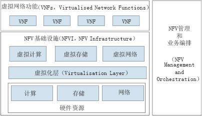
Figure 1 NFV architecture
The NFV architecture includes three core work domains: Virtual Network Functions (VNFs), NFV Infrastructure (NFVI), NFV Management and Orchestration (NFV Management and Orchestration), as follows:
(1) Virtual Network Functions (VNFs): Software that performs specified network functions, such as P/I/S-CSCF and HSS in an IMS network, running on NFVI. The function and status of an NE node are not related to whether it is virtualized or not. The physical network functions and virtualized network functions and the external operation and maintenance interfaces should be the same. A VNF can consist of multiple internal components. In this scenario, the same VNF can be deployed on multiple virtual machines or on the same virtual machine. Each virtual machine only runs one component of the VNF.
(2) NFV Infrastructure (NFVI): An environment that provides the deployment, management, and execution of VNFs, including hardware and software. Hardware resources include computing, storage, and network resources that provide processing, storage, and connectivity capabilities for VNFs through the virtualization layer. The virtualization layer abstracts the hardware resources and decouples the VNF software functions from the underlying hardware to ensure that the hardware resources are independent of the VNFs.
(3) NFV management and business arrangement: It includes three parts: business arrangement system, VNF management system and NFVI management system. Among them, the business orchestration system is responsible for the arrangement and management of NFV infrastructure and software resources, and provides network services on NFV; VNF management system is responsible for VNF life cycle management (such as establishment, update, expansion, and termination); NFVI management system is VNF Provides the ability to manage and control the computing, storage, and network resources it needs.
2.2 SDN Architecture and Key Technologies
SDN is a new type of network architecture. Its design concept is to separate the network control plane from the data forwarding plane and implement programmable control. The major standards organizations such as ONF and IETF have studied the SDN technologies according to their respective research fields and technical viewpoints, and have formulated corresponding standards. Although the specific technical solutions of major schools are not the same, the overall framework and key technologies followed are basically the same.
The typical SDN architecture is divided into three parts: application layer, control layer, and infrastructure layer, as shown in Figure 2:
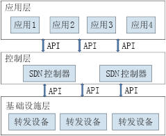
Figure 2 SDN architecture
(1) Application layer: Obtain the control right of the network through the interface provided by the control layer, and develop various business applications on the basis of it, so as to realize service innovation.
(2) Control layer: It is the concentration of network intelligence. It is responsible for maintaining the overall state of the network and the layout of data plane resources. It can flexibly and dynamically allocate resources for each user according to the different needs of users and the global network topology. The SDN Controller has a global view of the network, which is responsible for managing the entire network, communicating with the underlying network through standard protocols, and providing control of network resources to the application layer through an open interface.
(3) Infrastructure layer: It is a hardware device layer that focuses on simple data processing and forwarding.
3 IMS Core Network Virtualization Solution
The IMS network is composed of a service layer, a control layer, and an access layer. An open interface protocol is used between different layers to provide the SIP protocol-based multimedia session service control capabilities and service provision capabilities on the EPC and other IP bearer networks, including the service layer. The functions of network devices at all levels of the IMS network, including the control layer, access layer, and access layer, can be deployed and constructed through virtualization. Due to space limitations, this article will focus on the IMS core control layer network function virtualization program discussion.
The IMS core control layer mainly performs functions such as SIP session control, resource allocation, protocol processing, routing, authentication, accounting, and service triggering. The control layer functional entities include P-CSCF, I-CSCF, S-CSCF, AGCF, and HSS. SLF, MGCF, MGW, BGCF, ENUM/DNS, BAC, etc. Currently, these network entities are implemented based on the ATCA hardware architecture. Operators deploy the network according to the predicted traffic volume.
IMS core network element function virtualization re-designs the system and software architecture of core network elements such as P/I/S-CSCF and HSS so that it can run on the common server platform independently of the underlying hardware devices. Operators do not need to purchase dedicated hardware platforms when deploying IMS networks. Instead, they dynamically load, install, and run core network element software modules such as P/I/S-CSCF on the cloud platform according to the actual needs of the service. . The IMS virtualization logic architecture is shown in Figure 3:
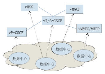
Figure 3 IMS virtualization logic architecture
IMS virtualization should provide the following four basic functions:
(1) One-click completion of IMS VNF deployment: According to predefined service templates and scripts, virtual network functions including all IMS core network elements of P/I/S-CSCF can be automatically implemented. Cloud platform loading and installation.
(2) Automatic extension of the IMS Virtual Network Function (IMS VNF): The virtual network function management system automatically monitors the KPI operating indicators of the virtual network function. Once the load of the virtual network function has been monitored to exceed the alert value, the virtual network function management system applies for resources such as calculation, storage, and network, and uses a predefined template and script to automatically install the relevant IMS virtual machine on the newly added virtual machine. Internet function.
(3) Automatic recovery of IMS virtual network function (IMS VNF): The virtual network function management system automatically monitors the KPI operation index of the virtual network function. Once the load of the virtual network function has been monitored to have fallen below the minimum value, the virtual network function management system notifies the virtual network function to be ready to shut down. After the preparation of the virtual network function is completed, the virtual network function management system will recover the allocated resources.
(4) Automatic disaster recovery protection of IMS virtual network function (IMS VNF): When a virtual machine running a virtual network function instance fails, a new virtual machine with the same virtual network function instance is automatically created to take over The faulty virtual machine bears the call.
4 Virtualized IMS Core Network Bearer Network Solution Based on SDN Architecture
4.1 Requirements of IMS Core Network Virtualization for Bearer Networks
The IMS system is an application system based on IP bearers. Therefore, the core network elements of the IMS network are connected through an IP network. In the existing IMS network deployment, network capacity and network routing organization are configured and designed according to the predicted traffic volume and service traffic flow during the network construction process. Each network element's IP bearer network bandwidth, port number, and IP address The needs of the address are clear and fixed. The IP bearer network only needs to provide network connections based on the specific bandwidth, ports, and routing requirements proposed by the IMS system. Unless there is an IMS network device out of network, its bearer network scheme does not need to change.
After the IMS network element functions are virtualized, each network element function is automatically loaded or unloaded on the common hardware platform in the form of software according to the actual needs of the user capacity change. The signaling process and the service flow between the IMS core network element functions and the terminals and core network element functions that provide IMS services remain unchanged. In other words, after the NE functions are virtualized, the functions and terminals of the NEs are still carried on the basis of the IP network. However, the requirements for bearers have undergone fundamental changes. After the IMS core network functions are virtualized, the requirements for the bearer network are as follows:
(1) After virtualizing the IMS core network functions, each NE function will be deployed in the operator's network function virtual infrastructure (NFVI) to share computing, network, and storage resources. Therefore, the IMS virtualization network function will be deployed in multiple data centers at the same time, and the network connection between the data center and the data center must be implemented.
(2) IMS network elements such as P/I/S-CSCF and MGCF are identified by SIP URIs, and the hop-by-hop SIP messages between network elements are made through DNS query to the IP address corresponding to the network element identifier of the next-hop network element. Routing and addressing. When the automatic deployment of the IMS virtual network function is completed with one click, it is necessary to assign an IP address and a SIP URI to each network element, and automatically generate a corresponding resolution relationship between each network element's IP address and SIP URI in the DNS in the IMS domain.
(3) When the network automatically expands the IMS virtual network function according to the change of traffic, some IMS users will be adjusted to access the new network element. This requires the automatic generation of each newly generated network element in the DNS in the IMS domain. In addition to the corresponding parsing relationship between the IP address and the SIP URI, the IP address and domain name mapping relationship of the newly added user access network element P-CSCF or BAC must also be automatically added to the DNS of the public network.
(4) When the network automatically reclaims IMS virtual network functions based on changes in traffic, some IMS users will be adjusted to access other network elements. This requires that the IP of the recovered network element be automatically deleted in the DNS in the IMS domain. Correspondence between the address and the SIP URI, and at the same time, the IP address and domain name mapping relationship of the reclaimed access network element P-CSCF or BAC is automatically deleted in the DNS of the public network, and the SIPURI of the adjusted user is added and its access is added. The correspondence between the IP addresses of network elements.
(5) When the IMS virtual network function performs automatic disaster recovery protection, the services of some IMS users will be taken over by new network elements. This requires that the IP address corresponding to the SIP URI of the failed NE be updated in the DNS in the IMS domain. Newly generated IP address of the NE. If the access network element undergoes disaster recovery switching, the IP address corresponding to the SIP URI of the to-be-taken user must also be changed to the IP address of the newly generated network element in the DNS of the public network.
4.2 IMS Core Network Virtualization Bearer Network Scheme
Each virtualized network function of the IMS core network has the features of automatic deployment, automatic expansion, automatic recovery, and disaster recovery protection. This requires that the bearer network of the data center where the virtualized network function is located automatically establishes a virtual private network for the IMS virtualized network function. Allocate network resources and IP addresses, provide dedicated network channels with QoS guarantees, and the virtual private network should also be able to cross data centers across domains.
Currently, the networking solutions in the data center and across the data center do not have the above capabilities. Therefore, the data center bearer network solution needs to be reconsidered.
The SDN architecture separates the control plane and the forwarding plane of the network, and realizes the automatic management of network resources, which can achieve the above functions well. The networking scheme based on the SDN architecture is shown in Figure 4.
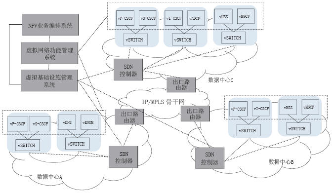
Figure 4 IMS core network virtualization bearer network
This architecture virtualizes physical network resources to form a virtual network. The virtual network is opened to the IMS virtualized network function in the form of services, and is responsible for carrying the service flow, thereby shielding the actual physical network. The SDN controller in the data center domain is responsible for managing the physical node devices such as switches and routers in the domain, and transmits the relevant information of the physical network to the virtual infrastructure management system through the northbound API. The virtual infrastructure management system then reorganizes the network topology and status of the entire virtual network based on the collected physical network topology information, manages the network resources of the virtual network, and opens related information to the virtual network function management system and service scheduling system. .
The IMS core network virtualization includes four basic application scenarios: automatic deployment, automatic expansion, automatic recovery, and disaster recovery protection. Due to limited space, this article describes only two scenarios: automatic deployment and automatic recovery. For automatic expansion scenarios, see Automatic deployment scenarios. For disaster recovery scenarios, refer to Automatic Expansion and Recovery Scenarios.
(1) One-click completion of the IMS Virtual Network Function (IMS VNF) deployment: The virtual network function management system submits the requirements for deploying the IMS virtual network functions to computing, storage, and network resources to the virtual infrastructure management system. When the virtual infrastructure management system receives the network resource requirements, it establishes a dedicated VPN for the IMS virtual network function according to the network resource usage of the virtual network, and allocates an IP address for the related network function. The virtual infrastructure management system issues related routing policies to the involved switches and routers through the SDN controller, and feeds back the resource allocation to the virtual network function management system. The virtual network function management system generates IMS virtual network functions such as P/S/I-CSCF based on the allocated resources, and at the same time, adds the corresponding resolution relations between the IP addresses of the respective network elements and the SIP URI in the DNS.
(2) Automatic recovery of IMS virtual network function (IMS VNF): After the function of the IMS virtual network to be recycled is closed, the virtual network function management system submits the recyclable computing, storage, and network resource requirements to the virtual infrastructure management system. At the same time, the corresponding parsing relationship between the recovered network element IP address and the SIP URI is deleted in the DNS. When the virtual infrastructure management system receives the request for reclaiming network resources, the corresponding network resources and IP addresses are recovered according to the network resource usage of the virtual private network, and the modified routing policy is delivered to the switch and the router through the SDN controller.
5 Concluding remarks
NFV and SDN are the new architectures that solve the problems of network-aware applications that cannot exist in existing networks, cannot deploy services flexibly in real time, cannot share infrastructure resources, and have high operating costs. They are unanimously recognized by the industry and are the direction of future network development. . Although NFV and SDN technologies have developed rapidly in recent years, they are still in the early stages of development. Most of the technical solutions of ONF/IETF/ETSI/OpenSource need to be further refined and verified from scale deployment.
Successfully ranked amongst the topmost business names of the industry, we are engrossed in presenting an optimum quality array of Solar Street Light Inverter.Owing to the efforts of our dedicated team of professionals, we have been constantly engaged in offering the best quality of Solar Light Inverter.
Inverter
Frequency Inverter,Solar Power Inverter,Pure Sine Wave Inverter,Car Power Inverter
Delight Eco Energy Supplies Co., Ltd. , https://www.cndelight.com