
The mobile music robot is based on the Infineon 16-bit microcontroller XE162FN processor. The 16/32-bit microcontroller developed by Infineon is highly system-integrated, requires no peripheral add-on devices and associated software overhead, provides system security and fault protection. Mechanism and other functions. Bluetooth is a global open, low-cost wireless communication specification. In addition, because Bluetooth has the advantages of long transmission distance, strong anti-interference ability, low power consumption and high transmission rate, the design adopts Bluetooth wireless communication technology, and the design body is a one-wheel mobile trolley robot, which has the following owner to walk and play music. Remote control operation, flashing lights with clap frequency and home security. The movement of the robot is driven by a DC motor to drive the wheel. The function of following the owner's walking is to determine the orientation between the handheld device and the mobile music robot in the hands of the owner by infrared emission and reception, and then drive the robot to follow the owner.
Wireless remote operation is implemented by Bluetooth communication. In terms of security functions, the mobile music robot is equipped with a typical smoke sensor for detecting fires, and if smoke or gas leaks are detected, the local sound alarm and the SMS sending module via the GSM wireless network send an alarm message to the designated cellphone number. The GSM network is a wireless digital network standard developed on the basis of cellular systems. It has large network capacity, complete service types, strong signal stability, high confidentiality and security, and flexible switching processing and automatic. There are many advantages such as roaming. In the design of the handheld device, a 320*240 touch screen is provided for intuitive and convenient keyless remote control, and an acceleration sensor senses the tilt angle to control the robot motion.
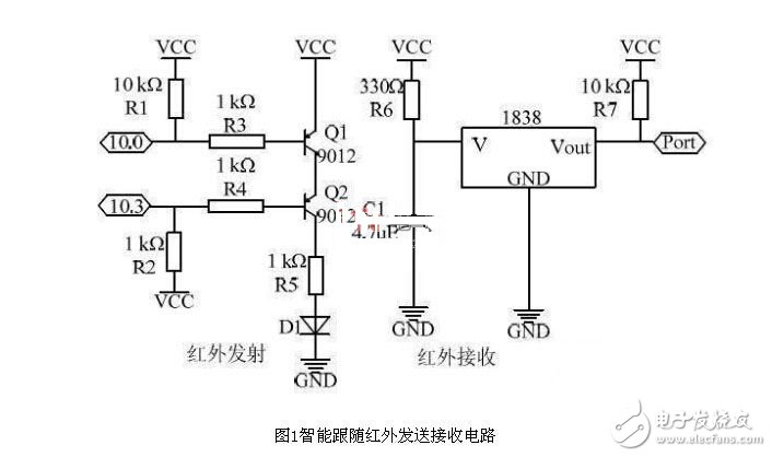
Receiving circuit
The intelligent follow-up function of the system is realized by infrared. When the infrared receiver on the music robot senses the infrared light, it will track the infrared emission source. When it is not sensed, it will rotate in-situ and search for the infrared emission source until the direction is repositioned. The infrared emission source is composed of 10 infrared emission tubes. The 10 infrared emission tubes are evenly placed on the surface of a sphere, so that the infrared emission source can radiate infrared rays in all directions, ensuring that the music robot can find the infrared emission source more quickly and accurately. The infrared transmitting tube emits a carrier wave with a carrier frequency of 38 kHz and a duty cycle of 50%. The infrared transmitting and receiving circuit is shown in Figure 1. 10.0 is connected to a common I/O pin to control the on and off of the infrared, that is, to turn on for 4 ms, then turn off for 11 ms, and repeatedly turn it on and off. Connect a PWM square wave with a square wave frequency of 38 kHz. There are 10 infrared transmitting tubes.
The infrared receiving device uses two infrared receivers 1838, which are respectively mounted on the head and the tail of the music robot. The output pins of the two receivers are connected to the 10.2 and 10.7 pins of the microcontroller. The infrared receiver 1838 is sensitive to infrared light at a frequency of 38 kHz, so the infrared receiver 1838 can detect the orientation of the infrared source, thereby driving the motor toward the source of the source.
Clap signal capture circuit design
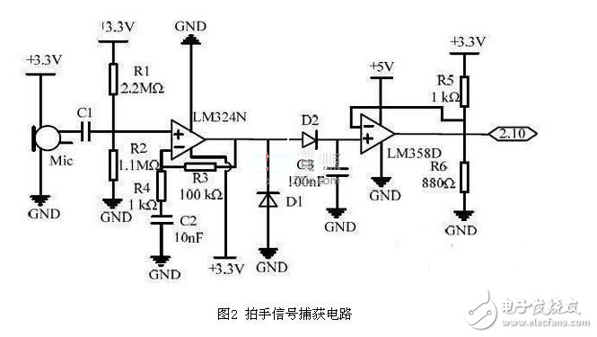
The realization of the clap light function is mainly divided into the capture of the clap signal and the rotation of the lantern. The rotation of the lantern is relatively simple, but the signal generated by the clap is not a standard step signal when the clap signal is captured. When the waveform is observed, in fact, the waveform has more burrs on the rising edge and the falling edge, that is, a clap signal generates multiple step signals. If the MCU records the time interval of 2 rising edges, due to the existence of the glitch, the MCU incorrectly captures the glitch as a rising edge, causing the time interval between the two rising edges to become smaller. The solution is to use the envelope detection circuit to perform envelope detection, and then select a suitable comparison voltage value through the voltage comparator to generate an ideal step signal, that is, a step signal is generated by one clap.
The circuit uses the microphone to collect the sound signal, and then uses the LM324 to scale up the acquired signal, the amplification ratio is 100 times, then take two 1N5819 and a 104 monolithic capacitor for envelope detection, and finally use LM358 as the voltage comparison. The voltage is obtained by dividing the voltage with a 1 K resistor and a 880 Ω resistor. The circuit is shown in Figure 2. The movement of the robot is realized by driving the DC motor to drive the wheel to rotate, that is, controlling the forward and reverse rotation and speed of the DC motor. The DC motor drive chip of the system adopts the L298N of SGS Company, and has a 4-channel logic drive circuit inside. The tri-type tube is used to form an H-type balance bridge, which has large driving power and strong driving capability. At the same time, the H-type PWM circuit operates in the saturation state and the off state of the transistor, and has very high efficiency.
DC motor drive circuit design
The speed of the motor depends on three factors: load, voltage and current. For a given load, the motor can be kept at a steady speed by pulse width modulation. The speed of the motor can be increased or decreased by varying the pulse width applied to the DC motor. Adjust the pulse width, that is, change the duty cycle and adjust the speed of the motor. The driver board uses 6 high-speed optocouplers 6N137 to isolate the driver circuit from the logic circuit, which can effectively avoid mutual interference between the driver circuit and the logic circuit. The circuit schematic of the driver board is shown in Figure 3.
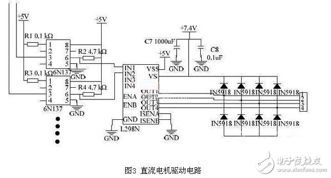
The software program can freely change the duty cycle of the two PWM pulses of the MCU. The A terminal of the motor is connected to the PWM pulse signal. The B end of the motor is connected to an I/O pin of the MCU. When this I/O pin is set, current flows from the B end of the motor to the A end of the motor. When this I/O pin is set to 0, current flows from the A end of the motor to the B end of the motor, so that the motor can Changing the direction of motor rotation and controlling the duty cycle value of the PWM pulse signal can also change the motor rotation speed to achieve steering and speed control.
Standard Type Disc Insulator is made of glass to support and insulate wires. Standard disc Vintage Glass Insulators are connected together for the power cord, one end is connected to the pole by fittings, and the other end is connected to a conductor or cable. The most widely used in Glass Insulator production lines are tempered glass insulators. We also sale standard disc Porcelain Insulator and standard disc type Suspension Insulator.
Standard glass insulators: U70, U100, U120
Breaking load between 40kN and 240kN
Frequencies up to 100 Hz are supported.
Temperature range is between -60°C and +50°C.
The insulators are made of an insulating element, a cap and a pin.
The cap and pin are made of high-strength hot galvanized cast-iron, with corrosion- resistant coverage, it can be of the type ball-socket or clevis-tongue.The lock, a split-pin is made of stainless steel or phosphor bronze.
Parameters
| Currency Designation | U70B/140 | U70B/146 | U70B/127 | U100B/146 | U100B/127 | U120B/146 | U120B/127 |
| Designation | LXP3-70 | LXP1-70 | LXP2-70 | LXP-100 | LXP2-100 | LXP-120 | LXP2-120 |
| Diameter D,mm | 255 | 255 | 255 | 255 | 255 | 255 | 255 |
| Spacing H,mm | 140 | 146 | 127 | 146 | 127 | 146 | 127 |
| Creepage L,mm | 320 | 320 | 320 | 320 | 320 | 320 | 320 |
| Socket Soupling,mm | 16 | 16 | 16 | 16 | 16 | 16 | 16 |
| Mechanical Falling Load,KN | 70 | 70 | 70 | 100 | 100 | 120 | 120 |
| Mechanical Routine Test,KN | 35 | 35 | 35 | 50 | 50 | 60 | 60 |
| Wet Power Frequency withstand voltage,KV | 40 | 40 | 40 | 40 | 40 | 40 | 40 |
| Dry Lighting Impulse withstand voltage,KV | 100 | 100 | 100 | 100 | 100 | 100 | 100 |
| Impulse Puncture Voltage,PU | 2.8 | 2.8 | 2.8 | 2.8 | 2.8 | 2.8 | 2.8 |
| Power Frequency Puncture Voltage,KV | 130 | 130 | 130 | 130 | 130 | 130 | 130 |
| Radio Influence Voltage,μv | 50 | 50 | 50 | 50 | 50 | 50 | 50 |
| Corona Visual Test,KV | 18/22 | 18/22 | 18/22 | 18/22 | 18/22 | 18/22 | 18/22 |
| Power Frequency Electric arc voltage | 0.12S/20KA | 0.12S/20KA | 0.12S/20KA | 0.12S/20KA | 0.12S/20KA | 0.12S/20KA | 0.12S/20KA |
| Net Weight per unit,KG | 3.6 | 3.6 | 3.5 | 4 | 4 | 4 | 4 |


We warmly welcome friends both domestic and abroad to visit our company, for more details about glass insulator, if you have any questions, please contact with us directly.
Standard Type Disc Insulator
Vintage Glass Insulators,Standard Disc Type porcelain Insulator,Standard Disc Type Suspension Insulator,Standard Type Disc Insulator
FUZHOU SINGREE IMP.& EXP.CO.,LTD. , https://www.cninsulators.com