
A variety of virtual reality (VR) and augmented reality (AR) near-eye display (NED) solutions are currently under development, and the viability of visual experiences brought about by the seamless integration of digital content and the physical world continues to increase. Let's take a closer look at some of the most challenging issues in designing a stunning perspective near-eye display to seamlessly integrate the digital world with the physical world.
In many cases, technical optimization of near-eye display solutions is not just a “better†problem, but an important issue that determines its usability. Imagine a surgeon or a medical first aid specialist wearing a near-eye display as an aid during treatment. In this environment, a clear, unobtrusive visual experience is essential. Or, imagine a video game player that requires a very low display delay to provide a seamless, real-time experience.
In both cases, a realistic visual experience depends on minimizing the latency (delay) of displaying the image, maximizing optical contrast and increasing the angle of view (FOV) of the displayed information.
Display latency - the key to creating a real-time experience
Considering system latency first, many system-level components generate delays that are integrated into the delay experienced by the user. To this end, we look at the parts related to the display engine and can divide it into the following two parts:
Display (pixel) delay = pixel data update time + pixel switching time
The first part, called "Pixel Data Update Time," is the time it takes for the display device to "load" the new data value into the display pixels. For many display engine architectures, this is one or more frame image cycles, measured from input to engine. If one frame is delayed, it is about 16.67 milliseconds for a 60 Hz source, which is commonplace for many modern display technologies, and it includes a frame memory that is convenient for image processing. For some display engines, the pixel data update time may be two or more frames.
The second part of the display delay is the "pixel switching time", which is the time it takes for a pixel to switch from a current state (on or off) to a reverse state. When the pixel is fully precipitated and the human observer can clearly perceive the new data, the pixel switching time ends.
The pixel data update time and pixel switching time are display total delay times perceived by human observers. A delay of 16.67 milliseconds is usually considered a good performance, and some show up to 60 milliseconds or more.
Texas Instruments' DLP® Pico chip has the fastest pixel speed available, flipping every digital micromirror (pixels) thousands of times per second, reducing display latency, supporting display frame rates up to 120Hz, while maintaining high picture quality quality.
Contrast - the key to the fusion of digital content and real-world vision
In addition to providing a low-latency real-time experience, the ideal near-eye display solution should provide transparent content with high definition that does not hinder the real-world look of end users. For example, if the data to be displayed uses only 20% of the display device pixel array, then the remaining 80% is actually invisible to the user, thereby merging the digital content with the real world.
Importantly, in a see-through near-eye display optical system, images are not displayed on a translucent surface (ie, on an ophthalmic lens). Since the surface is very close to the user's eyes by definition, the display on the translucent surface is ineffective and the human eye cannot comfortably focus on such close things. Instead of creating an image on one surface, the optical system creates a pupil that acts as the last component in the optical link - creating the final image on the retina of the eye.
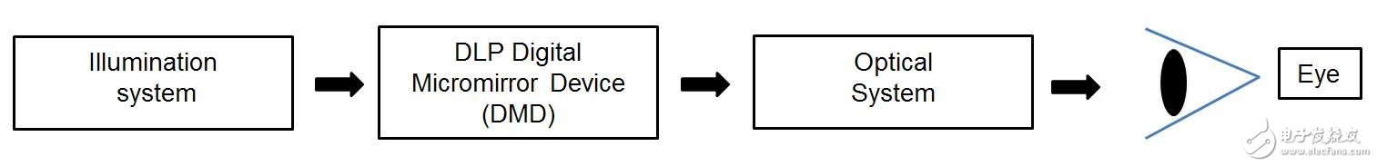
Lighting System - DLP Digital Micromirror Device (DMD) - Optical System - Human Eye
The conventional see-through NED optical system includes a waveguide optical element that collects the input light and transmits it to the human eye. This arrangement not only forms the necessary aperture, but also positions the microdisplay, optics and illumination without impeding the user's field of view.
Now that we understand the optical system, how do we ensure that the transparent area of ​​the displayed image does not interfere with the user's field of view? The best way to achieve this is to maximize the contrast of the optical system. The image below shows the display impact that contrast can bring, which is what the near-eye display user sees.
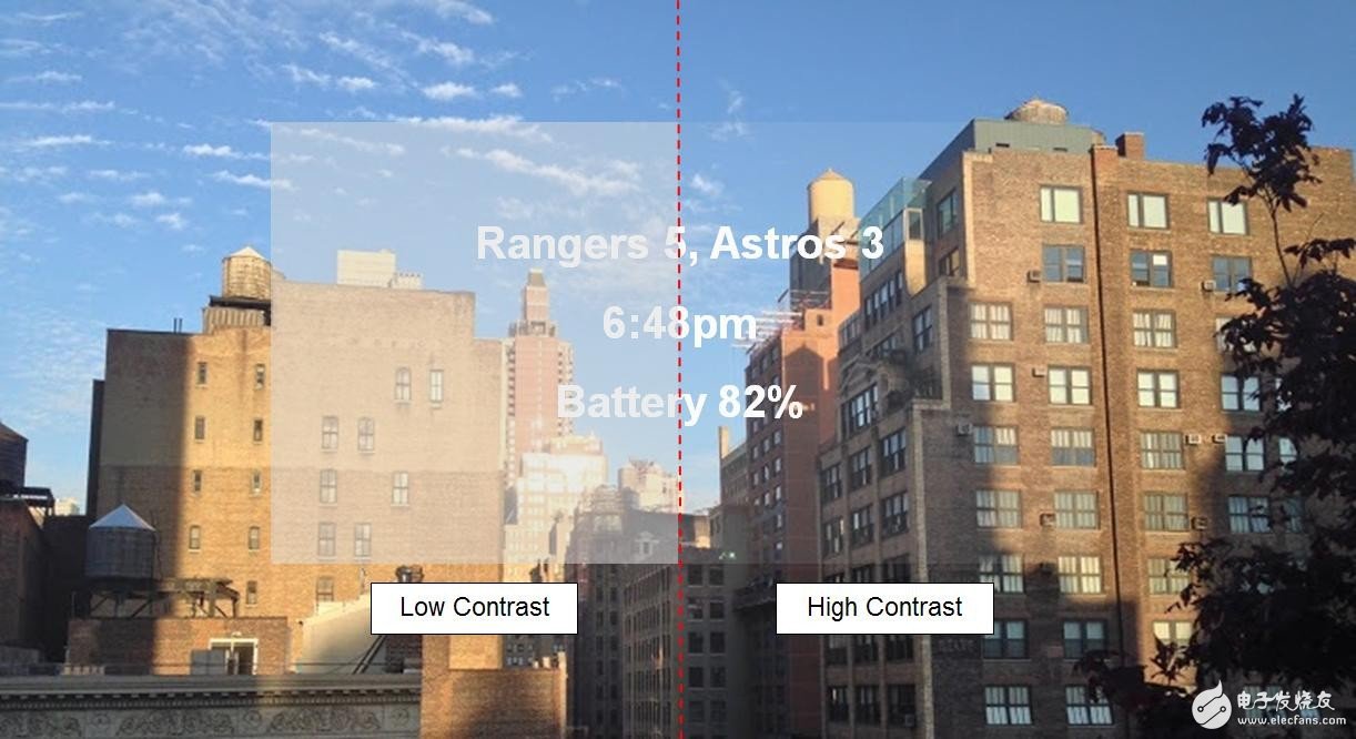
Note: The photo is an analog, non-actual near-eye display image
Low contrast and high contrast
Many of the elements in the near-eye display design can affect contrast, including the number of apertures (f-values) in optical design and advanced image processing algorithms. For some microdisplay devices, the fill factor also affects the contrast, but usually the impact is lower.
The f-value of the optical design illustrates the ratio of the focal length of the lens to the diameter of the incident via. Higher f-numbers result in higher contrast - and reduce optical complexity and downsizing. Although a high f-value can result in higher contrast, it must also be balanced with the required viewing angle - because a higher f-value not only increases contrast but also reduces viewing angle.
Advanced image processing technology can also improve contrast by intelligent management of RGB backlights (ie, LED brightness) combined with the digital gain obtained with each image frame. For example, Texas Instruments DLP Products' TRP chip features the IntelliBrightTM algorithm, which includes what is known as Content Adaptive Illumination Control (CAIC). The algorithm intelligently adjusts the brightness of the image based on image content and ambient lighting conditions. This not only produces optimal image brightness and contrast, but also optimizes system power consumption; this is another important advantage of near-eye display technology.
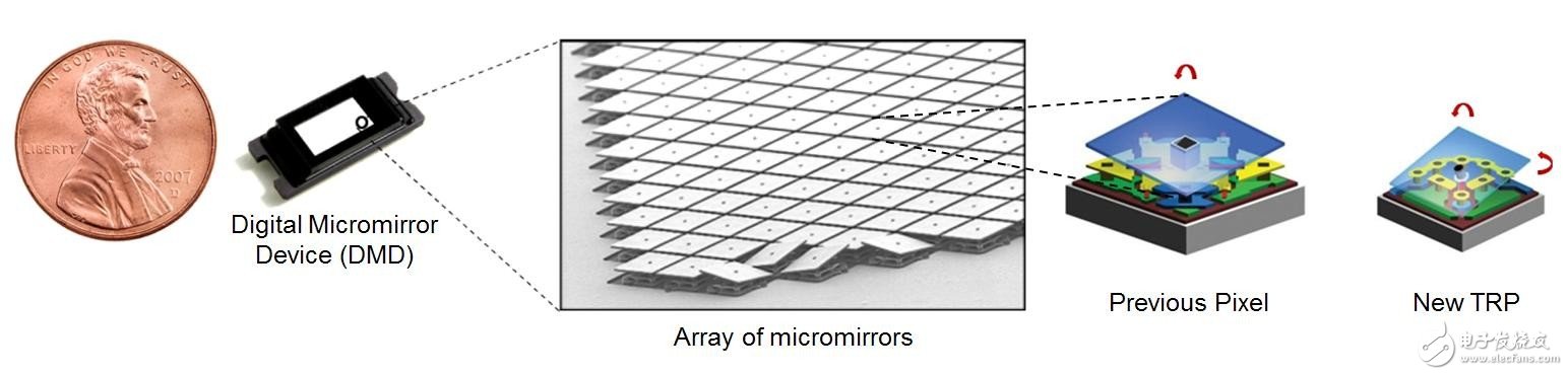
Digital Micromirror Device (DMD) Micromirror Array Front Pixel New TRP
Maintain a natural perspective visual experience with a larger perspective
The human eye has a horizontal viewing angle of almost 180 degrees. Augmented reality headsets typically have a viewing angle of 20-60 degrees, which is sufficient to produce a natural viewing experience. In contrast, the typical penetrating smart eye solution has a small viewing angle, so that the user must periodically and unnaturally pay attention to it. The trend for most perspective near-eye display applications is a larger viewing angle. A larger viewing angle can also allow more content to be superimposed with the user's natural observations of the real world, providing a higher quality visual experience.
The viewing angle is typically controlled by three key design elements: the diagonal dimensions of the microdisplay array, the optical f-value, and the pupil size at the waveguide end. There are several trade-offs between these factors: larger array diagonal dimensions provide higher viewing angles and, in most cases, higher resolution, but this also increases the size of the system because diagonal Line sizes are often converted to larger optics. A lower f-value optical design produces a larger viewing angle, but also increases optical size and contrast. As the pupil size increases, the viewing angle decreases. For example, a 5 mm pupil can achieve a 45 degree viewing angle, while a 10 mm pupil can achieve a viewing angle of less than 25 degrees with the same f value.
For many perspective near-eye display solutions that are still under development, it is important to provide a visual experience that seamlessly integrates digital content with the physical world. Design challenges require a trade-off between factors that directly affect the end user's experience. For more on these balances, check out the DLP Technical White Paper for Nearsightedness and visit the TI E2ETM Community DLP Products and MEMS Forum to explore design solutions with Texas Instruments experts.
Spinning is to fix the flat or hollow billet to the die of the spinning machine. While the billet rotates with the spindle of the machine tool, the billet is pressed with a rotating wheel or a driving rod to make it produce local plastic deformation. Spinning is a special forming method. The drawing, flanging, shrinkage, bulging and flanging of rotating bodies of various shapes can be completed by spinning method.
Spinning Process,Aluminum Spining Light Cover,Metal Spinning Processing,Stainless Steel Spinning Processing
Dongguan Formal Precision Metal Parts Co,. Ltd , https://www.formalmetal.com