
0 Preface
The structure and working principle of the switched reluctance motor (SRM) are relatively simple, the fault tolerance performance is good, and a small torque can be obtained at a low speed to obtain a large torque. The high-speed constant power region has a wide range and can be used in a coal mine. Textile, chemical, electric vehicles and other places with harsh working conditions. However, due to the SRM stator, the doubly salient structure of the rotor, the non-sinusoidal characteristics of the winding current, and the deep saturation of the core flux density, the smooth control of the SRM is difficult to achieve, especially in reducing the noise during operation. The current common SRM control systems tend to focus on a single aspect of motor performance and do not provide a good overall adjustment of multiple parameters. If the control system can reflect the important parameters of the SRM in the running state in real time and carry out the overall analysis, the work efficiency will be greatly improved. The virtual instrument has powerful data processing capability and friendly operation interface. At the same time, its development cycle is short and the volume is small, which has attracted more and more attention.
The data in this article was obtained by using the PCI-6143 data acquisition card introduced by National Instruments of the United States and writing programs in LabVIEW 8.6 for the development environment. Considering that the system may be used in a harsh working environment, in order to achieve real-time control more safely and effectively, the DSP is used as a backup processor of the PC. The experimental prototype is an 8/6 pole SRM with a power of 150 W.
1 Switched reluctance motor monitoring system
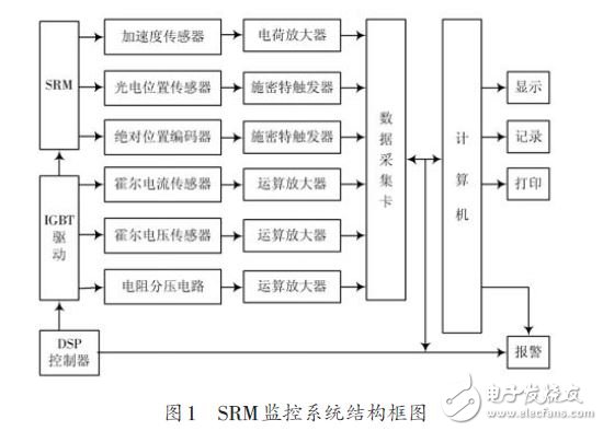
The SRM operation monitoring system is mainly composed of SRM drive system and various sensors, data acquisition cards, PCs and DSPs. The system structure block diagram is shown in Figure 1.
1.1 Phase voltage signal detection
The phase voltage is an important parameter that reflects the SRM start, stable operation, speed regulation or braking state. The Hall voltage sensor is used to measure the phase voltage as the main measurement loop. The primary coil of the Hall voltage sensor is connected in parallel to both ends of a phase winding of the motor. In order to make it work at its best, a suitable size resistor, preferably an adjustable resistor, should be placed in series with the primary coil. The secondary coil of the Hall voltage sensor is connected in series with a precision resistor of appropriate resistance, which is processed by an operational amplifier and then connected to the data acquisition card.
Considering that the Hall sensor is easily burned out when the voltage is overvoltage, a resistor divider circuit is used as the standby voltage measurement loop. By measuring the voltage across the voltage divider resistor, the SRM phase voltage can be derived. This method is simple and easy, but the accuracy is relatively low. It should be noted that the optocoupler needs to be isolated between the measurement circuit and the main circuit to avoid mutual influence between the two circuits.
1.2 Phase current signal detection
According to the law of electromagnetic induction, there is a magnetic field around the energized wire, and its magnitude is proportional to the current in the wire. Therefore, the magnetic field can be measured by the Hall effect, and the current in the wire can be determined. The Hall current sensor can measure the SRM phase current more accurately, and the measurement circuit is isolated from the main circuit without electrical contact, which is a safe measurement method. Hall current sensors are also more susceptible to damage when overcurrent occurs. Therefore, in each phase winding, a resistor having a relatively small resistance value but high precision and power is connected in series. By measuring the voltage at the resistor terminal, the winding current can be sensed. Of course, its accuracy is also relatively low, but it can also be used as a backup circuit for current measurement.
The phase current waveform of the SRM has a relatively large change depending on the operation mode and operating conditions, and pulsation occurs. In order to reflect the current change as much as possible, it is necessary to set the sampling frequency of the data acquisition card to be relatively large, preferably above 10 kHz. In addition, the detection circuit should also have the characteristics of fast performance, wide detection frequency range, and good isolation between the main circuit and the control circuit. The current detection circuit mainly realizes two functions of current observation and overcurrent protection.
Noise Cancelling Earphonecan be used simultaneously, also one of them can be used separately. And can connect two devices simultaneously. HD Microphone, provide clear and loud sound.
with cvc 6.0 noise cancellation, you can enjoy clear calling and music by tsuneo x3t earbuds. The in-ear Bluetooth Earphones adopt tws technology to eliminate noise and echo. High quality chip for stereo sound and bass sound . It's easy to take and make calls, voice dialing with superior microphone quality. Ideal for car calling and friends chatting, or working use.
Noise Cancelling Earphone
Noise Cancelling Earphone,Noise Cancelling Headphones,Noise Cancelling Headset,Bluetooth Earphone For Iphone
ShenDaDian(China) Digital Electronics Co.,Ltd , http://www.btearbuds.com