
Several basic types of switching power supplies
As the name suggests, switching power supplies use electronic switching devices (such as transistors, FETs, thyristors, etc.), through the control circuit, so that the electronic switching device is constantly "on" and "off", let the electronic switch The device modulates the input voltage to achieve DC/AC, DC/DC voltage conversion, and adjustable output voltage and auto-regulation.
Switching power supplies generally have three modes of operation: frequency, pulse width fixed mode, fixed frequency, variable pulse width mode, frequency, pulse width variable mode. The former working mode is mostly used for DC/AC inverter power supply or DC/DC voltage conversion; the latter two working modes are mostly used for switching regulated power supply. In addition, the switching power supply output voltage also has three working modes: direct output voltage mode, average output voltage mode, and amplitude output voltage mode. Similarly, the former mode of operation is mostly used for DC/AC inverter power supply, or DC/DC voltage conversion; the latter two modes of operation are mostly used for switching power supply.
According to the way in which the switching devices are connected in the circuit, the switching power supplies which are widely used at present are generally classified into three types: a series switching power supply, a parallel switching power supply, and a transformer switching power supply. Among them, the transformer type switching power supply (hereinafter referred to as the transformer switching power supply) can be further divided into: push-pull type, half-bridge type, full-bridge type, etc.; according to the excitation of the transformer and the phase of the output voltage, it can be further divided into: forward type , flyback, single-excitation and double-excited, etc.; if divided into uses, they can be divided into more categories.
Series switching power supply
How the series switching power supply works
Figure 1-1-a is the simplest working principle diagram of the series switching power supply. In Figure 1-1-a, Ui is the operating voltage of the switching power supply, namely: DC input voltage; K is the control switch, and R is the load. When the control switch K is turned on, the switching power supply outputs a pulse voltage Up having a pulse width Ton and an amplitude of Ui to the load R; when the control switch K is turned off, it is equivalent to the switching power supply outputting a pulse to the load R. A pulse voltage with a width of Toff and an amplitude of zero. Thus, the control switch K is constantly "on" and "off", and a pulse-modulated output voltage uo can be obtained across the load.
Figure 1-1-b is the waveform of the output voltage of the series switching power supply. As shown in the figure, the output voltage uo of the control switch K is a pulse-modulated square wave, the pulse amplitude Up is equal to the input voltage Ui, and the pulse width is equal to the control switch K. By turning on the time Ton, the average value Ua of the output voltage uo of the series switching power supply can be obtained as follows:
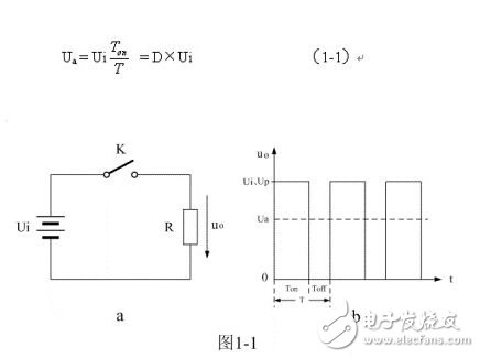
Waveform diagram of output voltage of series switching power supply
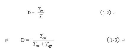
In the formula, Ton is the time when the control switch K is turned on, and T is the duty cycle of the control switch K. By changing the ratio of the control switch K on time Ton to the off time Toff, the average value Ua of the output voltage uo can be changed. Generally, people call it duty (Duty), which is represented by D, namely:
The amplitude of the output voltage uo of the series switching power supply is equal to the input voltage Ui, and the average value Ua of the output voltage uo is always smaller than the input voltage Ui. Therefore, the series switching power supply generally outputs the voltage with the average value Ua as a variable. Therefore, the series switching power supply belongs to a step-down switching power supply.
The series switching power supply is also called a chopper. Because of its simple working principle and high working efficiency, it is widely used in output power control. For example, electric motorcycle speed controllers and light brightness controllers are all applications of series switching power supplies. If the series switching power supply is only used for power output control, the voltage output can be connected to the rectifier filter circuit without directly connecting the power supply to the load; however, if it is used for the regulated output, it must be rectified and filtered.
The disadvantage of the series switching power supply is that the input and the output share a ground. Therefore, it is easy to generate EMI interference and the bottom plate is charged. When the input voltage is the commercial rectified output voltage, it is easy to cause electric shock and is not safe for the human body.
Series switching power supply output voltage filter circuit
Most switching power supply outputs are DC voltage. Therefore, the output circuit of a general switching power supply has a rectifying and filtering circuit. Figure 1-2 shows the working principle of a series switching power supply with rectification filtering function.
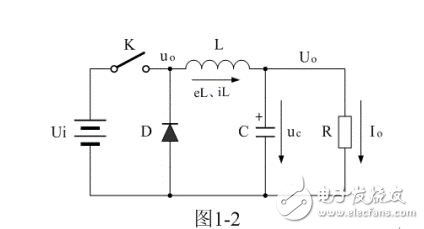
Working principle diagram of series switching power supply with rectification and filtering function
Wall Mount Power Adapter mostly use as a small power source for portal electrical device . Our wall mount power range is from 3W to 48W ,All Power Adapters comply with global.
High quality ,competitive price and good servie, MLF welcome you. Please don't hesitate contact us if there is any question on the perfomance of switching power adapter .
Wall Mount Power Adapter
Wall Mount Power Adapter,Wall Adapter Power Supply,Wall-Wart Power Supply,Wall Adapter
Meile Group Limited , https://www.hkmeile.com