
introduction
With the rapid development of LED technology, LED lighting products, especially high-power LED lighting products, are becoming a new generation of light sources, but the problems of lighting packaging and application have emerged. The most important thing is how to solve the problem of high-power LED lighting. The problems caused are not only related to technical performance problems in structural design and engineering applications, but also related to heat dissipation leading to safety insulation problems.
1 Analysis of heat generation and heat dissipation during LED operation
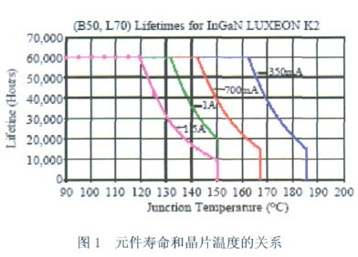
In order to make the LED emit brighter light, it needs to input higher power. However, the current photoelectric conversion efficiency (WPE) value of the high-power LED is still limited, generally only about 15~25% of the input power becomes Light, the rest will be converted into heat. Since the area of ​​the LED chip is small (~1mm2), the heat generation (heating density) per unit area of ​​the high-power LED is very high, even more serious than the general IC component, and the junction temperature of the LED chip (Junction Temperature) Greatly improved, it is easy to cause overheating problems. Excessively high junction temperature of the wafer will reduce the luminance of the LED, with the red light being most pronounced. It will also cause the wavelength shift of the LED to affect the color rendering, and the LED reliability will be greatly reduced. As shown in Figure 1, the heat dissipation technology has become the bottleneck of the current LED technology development.
Therefore, the design of the heat dissipation has great challenges. From the wafer level, the package level, the PCB level to the system module level, the heat dissipation design must be highly valued and an optimal heat dissipation solution should be sought. For LED lighting products, the heat dissipation requirements of other levels are more obvious due to the greater heat dissipation limitations at the system side. For the LED heat transfer problem, the most basic analysis method is to use the thermal resistance network for analysis. That is to construct the thermal resistance network from the main heat dissipation path of the LED heat source to the ambient temperature, and then analyze the characteristics and size of each thermal resistance value, so that the wafer temperature in the ideal condition can be estimated, and the thermal resistance network is used under various parts. Countermeasures to reduce the thermal resistance value. Current thermal design with better wafer-to-package level performance, including:
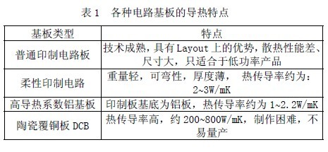
1.1 The design of a common fusion gold substrate and flip chip form makes it easier to transfer heat from the wafer to the package. Increasing the size of the wafer to reduce the heat density is also a viable direction. The thermal conductivity of various circuit substrates is shown in Table 1.
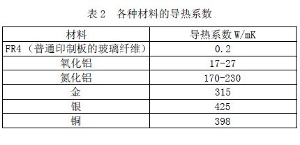
1.2 In the package heat dissipation design technology, the heat sink of high thermal conductivity metal (Al, Cu...) is utilized. The thermal conductivity of various materials is shown in Table 2.
1.3 High thermal conductivity ceramic substrate (AlN, SiC⋯.) and other designs can quickly spread the heat of the wafer, effectively reducing the thermal resistance of the package.
1.4 In the heat dissipation design of the PCB level, the difference from the traditional PCB is mainly due to the high heat density of the LED. The heat dissipation capability of the traditional FR4+ copper foil layer is limited. Therefore, the thicker metal layer is needed to reduce the diffusion heat resistance (SpreadingResistance) ), this structure is called MCPCB (Metal Core PCB). The basic structure of the MCPCB includes a thicker metal layer, a dielectric layer, and a copper foil layer. The heat of the package can be further diffused and quickly transferred to the heat dissipating components of the system module to reduce the thermal resistance.
1.5 In order to reduce the thermal resistance of components, some designs use Chip-onboard design to directly design LED chips on MCPCB, and reduce the thermal resistance of packaging materials and Solder interface materials, thus improving the heat dissipation effect. Many companies currently have products. This design is also used (Lamina Inc., Citizen Inc., OSRAM Inc, Avago Technologies...). However, such a design increases the difficulty of optical design and causes manufacturing reliability problems, and is complicated in design.
1.6 The heat dissipation design of the heat dissipation module, due to the limited heat dissipation capability of the natural convection, the thermal resistance from the heat dissipation module to the air generally accounts for a heavier proportion. Unlike electronic products, the general electronic product system has vents, so the PCB can transmit heat to the air through convection and radiation, and many of the LED lighting products are sealed, thus limiting the heat dissipation capability of the components. Since the ability of the heat dissipation module to take away heat has a great relationship with the heat dissipation design method, how to meet the requirements of the traditional lamp, increase the contact area with air, increase the convection coefficient or increase the radiant heat transfer effect is the main design direction.
1.7 Heat pipe heat conduction. In many cases, it is necessary to transfer the heat generated by the LED to the heat sink as quickly as possible. This is especially important in the use of integrated monolithic high-power LEDs because of its high heat (up to 50W-100W). Very concentrated (sometimes only 30mm), this time you can use heat pipe to dissipate heat. The heat pipe is also called a phase change heat exchanger because the liquid therein changes from a liquid phase to a gas phase to conduct heat. Its thermal resistance is very small, only about 0.065 ° C / W.
2 Analysis of the relationship between structure, heat generation and safety insulation of common LED products
In order to facilitate replacement and cost saving, the shape of the general LED luminaire is basically the same as that of the traditional luminaire. For example, the lamp head similar to the ordinary incandescent lamp E27 or E14, and the length of the traditional fluorescent lamp tube and the size of the lamp ends at both ends conform to the national standard, so that it is convenient and direct. Replacing the traditional light source, reducing or eliminating the modification of the original luminaire, which also causes the driving power of almost all LED bulbs or LED light pipes on the market to be built-in, that is, the driving power source is placed inside the light source, the driving power source and the LED Heat is generated during operation, and the heat of the two will overlap each other, making the drive power and LEDs hotter, which in turn affects the performance and life of the drive power and LED. As the power increases, the waste heat in the electric heat flow generated by the LED cannot be effectively dissipated, resulting in a serious decrease in luminous efficiency.
The definition of LED lifetime is: when the LED luminous efficiency is lower than 70% of the original luminous efficiency, it can be regarded as the end of LED life. LED luminous efficiency will decrease with the use time and frequency, while too high junction temperature will accelerate the LED luminous efficiency attenuation. With the maturity of chip technology, the input power of a single LED chip can reach 5W or even higher. Therefore, it is more and more important to prevent the LED from operating at too high a temperature. If the heat of the chip cannot be effectively dissipated, the thermal effect will become more and more obvious, which will increase the junction temperature of the chip, thereby directly reducing the photon energy emitted by the chip and reducing the light extraction efficiency. The increase in temperature also causes the chip to accelerate aging, light decay, color shift, and the emitted spectrum is red-shifted, and the color temperature quality is degraded.
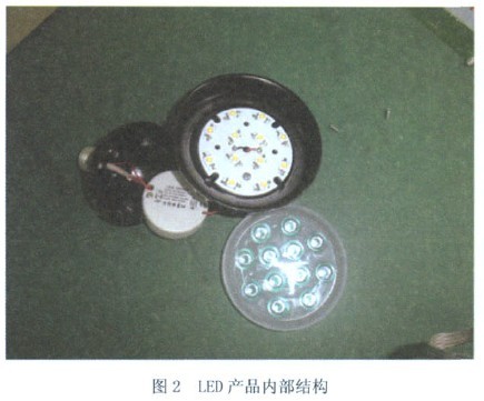
At present, the high-power LED light source on the market generally adopts the "chip-aluminum substrate-heatsink three-layer structure mode", that is, the chip is first packaged on an aluminum substrate to form an LED light source module, and then the light source module is placed on the heat sink. Most of the high-power LED lighting source components are made of metal materials, including aluminum alloy casings and aluminum substrates. For example, Figure 2 shows the internal structure of a typical LED product. We can see the lamp body from the casing to the casing. The internal aluminum substrate is almost all-metal structure, and the use of a large amount of metal enhances the heat dissipation capability of the LED light source module. However, if the design, manufacturing process, material usage, power quality, etc. are slightly inadvertent, these metal parts can easily lead to a decrease in the safety insulation performance, resulting in a test that does not pass the dielectric strength. In practical applications, the safety insulation can be improved to meet the standard requirements in terms of design, manufacturing process, material adoption, drive power quality, etc., such as changing the distribution position of the LED chip, increasing the creepage distance, and thickening the thickness of the aluminum substrate insulation layer. Use a better quality drive power supply, add insulation ring on the outer ring of the aluminum substrate, add insulation and heat dissipation coating on the contact surface between the aluminum substrate and the outer casing.
According to the requirements of GB 24906-2010 "Safety requirements for self-ballasted LED lamps above 50V for general lighting", LED products with a rated voltage of 220V in China need to have a voltage of 4000V between the lamp cap and the accessible parts after the tide test. In the pressure test, since the LED illumination source often uses a metal casing for heat dissipation, it is more likely to cause breakdown than a conventional lamp using a glass, plastic, ceramic, or the like. Similar requirements are also found in the standard IEC 62560:2011. For LED products rated at 220V, a voltage with a voltage of 2920V is required between the lamp cap and the accessible parts.
It can be seen that LED lamps have higher heat dissipation requirements than conventional lamps. To improve heat dissipation, a large number of metal parts are used to facilitate heat dissipation, but the safety insulation is also reduced. A little careless, it is easy to cause the dielectric strength of the LED lamp to fall below the standard requirements, and in actual testing, it is often found that even after passing the dielectric strength test, the LED chip often has a dark leakage phenomenon, which shows that LED luminaires have higher requirements for safety insulation than conventional luminaires. Therefore, in design, process, and manufacturing, it is necessary to deal with the relationship between heat dissipation and safety insulation of LEDs. The two are contradictory and a unified and coordinated relationship, which must be paid enough attention by designers, manufacturers and users to improve LEDs. The efficiency of the lamp enhances the safety of the LED lamp, and the promotion and application of the LED lamp can make great progress.