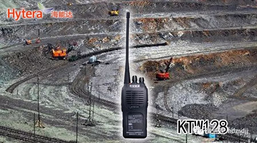
First, an analog walkie-talkie typically consists of several core functional modules. These include the transmission module, the reception module, the modem module, the signaling module, and the power control module. Each of these components plays a crucial role in ensuring the device functions properly and efficiently.
Second, the basic working principles of these modules are as follows:
1. Transmission Module: The process begins with the generation of the RF carrier signal using a phase-locked loop (PLL) and a voltage-controlled oscillator (VCO). This signal is then amplified through a series of stages—buffer amplification, excitation amplification, and power amplification—to reach the required output power level. Before being sent to the antenna, the signal passes through a low-pass filter to suppress unwanted harmonics, ensuring a clean transmission.
2. Reception Module: The receiving section usually operates in a double-conversion superheterodyne configuration. When a signal is received via the antenna, it goes through a transceiving circuit and a low-pass filter before entering a bandpass filter. The signal is then mixed with a local oscillator signal from the PLL frequency synthesizer, producing an intermediate frequency (IF) signal. This IF signal is filtered again to remove adjacent channel interference, and then processed further by an IF chip. A second mixing stage generates a second IF signal, which is filtered and amplified before being converted into an audio signal. This audio signal undergoes additional processing such as filtering, de-emphasis, and amplification before being sent to the volume control and power amplifier circuits, ultimately driving the speaker to produce sound.
3. Signaling Module: Early walkie-talkies did not require complex signaling systems, allowing users simply to tune to a specific channel and press PTT to communicate. However, modern devices often use CTCSS (Continuous Tone Coded Squelch System) to prevent unwanted transmissions. A microcontroller or dedicated chip generates the CTCSS tone, which is modulated onto the RF signal. Upon receiving the signal, the system demodulates the low-frequency tone, filters it, and compares it to a preset value. If it matches, the speaker is activated; otherwise, it remains muted, improving user experience by reducing background noise.
4. Modulation and Modulation Circuit: The voice input from the microphone is converted into an electrical audio signal. This signal is then amplified, passed through a pre-emphasis circuit, and filtered to ensure clarity. It is finally used to directly modulate the VCO, enabling the RF signal to carry the voice information.
5. Power Control: The CPU manages different power states to optimize battery life. For example:
(1) Receiving Power: Operates in intermittent mode to save energy when no transmission is needed.
(2) Transmitting Power: Activated only when the user presses PTT to send a message.
(3) CPU Power Supply: Maintains a stable power supply to ensure consistent operation of the control unit.

Rack Battery,Solar Rack System,Lithium Battery 5Kwh,Rack Mounted Battery
JIANGSU BEST ENERGY CO.,LTD , https://www.bestenergy-group.com
