
0 Preface
In recent years, with the development of mobile communication systems, radar systems, and ultra-wideband communication systems, filters of miniaturization and wide stopband performance have received extensive attention in practical applications. The parasitic passbands of the conventional parallel branch line low-pass filter and the half-wavelength parallel coupled line filter are both located at twice the center frequency, while the parasitic passband of the conventional step-impedance resonant filter is 2.5 times the center frequency. Left and right, it is difficult to obtain a wide stop band suppression effect when applied. Moreover, the size of such a filter is large, the stop band is narrow, and the performance of the filter is limited by the minimum width of the microstrip processing. In order to obtain steep attenuation edges and better stopband characteristics, it is necessary to increase the number of shorts or open stubs, but this will further increase the circuit size and introduce more insertion loss in the passband. Better frequency selection characteristics and out-of-band rejection can be obtained by introducing transmission zeros at finite frequencies. In the design of the filter, cross-coupling is widely used to introduce finite transmission zeros in the stop band. These transmission zeros can improve the band edge transition characteristics and the stop band rejection.
In this paper, the structural principle of the step-impedance resonator and the principle of the third-order cross-coupling structure are analyzed firstly. Then a design scheme of the miniaturized wide-stopband microstrip bandpass filter is proposed. The parasitic passband is about 4 at the center frequency. Double, it has a wider stop band than the general filter, and the simulation and measured results are analyzed, and the consistency is obtained.
1 Basic design theory
1.1 Step Impedance Resonator Principle
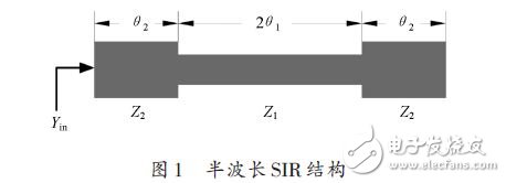
Step impedance resonators often use three basic resonant structures of λg /4 type, λg/ 2 type or λg type. The basic structure of λg /2 type resonator is shown in Figure 1. It is a non-isoelectric length half-wavelength structure. The characteristic impedance consists of transmission lines of Z1 and Z2, respectively, and their corresponding electrical lengths are θ1 and θ2.
If you ignore the step discontinuity in the structure and the edge capacitance at the open end, the input admittance Yin from the open end is:
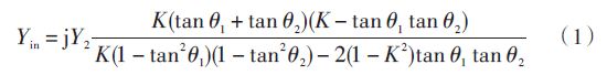
Where: K is the impedance ratio, defined as K = Z2 Z1. For the convenience of design, taking θ1 = θ2 = θ, then equation (1) is simplified as:
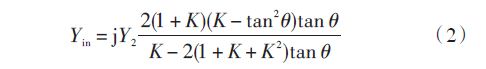
The resonance condition is: Yin = 0, and the fundamental frequency oscillation condition is K = Z2 Z1 = tan 2θ. From this formula, the resonance condition of the step impedance resonator depends on the electrical length θ and the impedance ratio K.
1.2 Third-order cross-coupling structure principle
For a narrowband filter, the equivalent circuit of the third-order cross-coupling filter is shown in Figure 2.
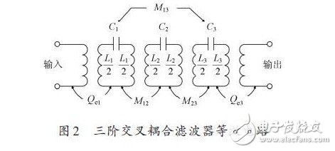
The coupling between adjacent resonators is represented by M12 and M23, and the cross coupling is represented by M13. The external quality factors Qe1 and Qe3 each represent input and output coupling. The coupling filter equivalent circuit shown in Figure 2 can be converted into a low-pass prototype filter form, as shown in Figure 3.
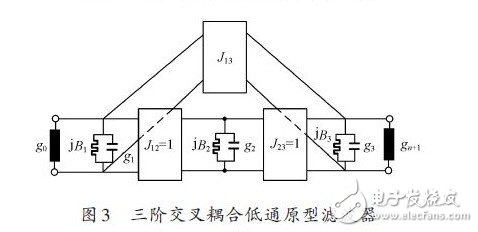
Each of the rectangular boxes represents a J-transfer converter of constant frequency. In a symmetric two-port circuit, J12 = J23 = 1, g0 = g4 = 1, g1 = g3, B1 = B3.
Screen Resolution
There are generally three screen resolutions for office projectors:
One is a 4:3 screen suitable for office PPT playback. The first is the SVGA machine with the lowest price and the highest cost performance. This kind of machine is generally priced at around 2500 and has powerful performance. The disadvantage is that the resolution is 800X600, which is relatively low. The second is the XGA machine, which is an upgraded version of the SVGA machine with a resolution of 1024X768.
The other is the 16:10 aspect ratio screen used by some foreign-funded enterprises, which is the 1280X800 resolution of WXGA. However, with the transparent price of 1080p projectors, more and more companies will choose full HD 1080p projectors as their office projection solutions.
Office Projector Features
According to the needs of different office environments, office projectors are roughly divided into three categories.
One is a conventional projector that is placed or hoisted in the conference room, the second is a Portable Projector that can be carried around, and the third is an ultra-short-throw projector that is convenient for work reports and speeches.
Wireless Office Projector
With the advent of the Internet era, the emergence of a series of wireless office series has added new members to the office projectors. The wireless office projector is realized by the built-in wireless module of the ordinary office projector. Wireless office makes people do not need to switch signal lines frequently in office meetings, allowing people to have a better experience in meetings!
office projector,projector for office use,projector at office depot,home office projector,hd office projector
Shenzhen Happybate Trading Co.,LTD , https://www.happybateprojectors.com