
Abstract: In view of the increasing demand for anti-theft and positioning of automobiles, based on the technology of single-chip microprocessor, GPS, GPRS, etc., the car anti-theft alarm system is designed with modular design scheme, realizing the function of real-time positioning and SMS alarm, namely system acquisition. After the vehicle is stolen, the GPS positioning module is activated to receive the vehicle location information (latitude, longitude, etc.), and the single-chip computer analyzes and processes the positioning data, and then sends the message to the owner's mobile phone through the GPRS network. Through software and hardware debugging, the system operation data shows that the system has strong real-time performance and high accuracy. The vehicle alarm response time is second-order delay, and the positioning error is within 0.6 degrees of latitude and longitude.
This article refers to the address: http://
With the rapid development of the economy, cars have begun to enter thousands of households. At the same time, car theft is also increasing day by day. The theft of a car is a huge loss for the owner. Therefore, car anti-theft systems and car positioning systems have a huge market demand.
Some vehicle anti-theft systems on the market currently have the disadvantages of single function, large volume and high energy consumption, which makes the vehicle still have certain safety hazards. Therefore, how to improve the existing car anti-theft alarm device, so that it can better achieve the alarm function, protect the private property of the people, has attracted the attention of many scholars and electronics manufacturers. Therefore, based on single-chip microcomputer, the vehicle anti-theft alarm system is designed by GPS/GPRS technology, which realizes the reliability of the vehicle positioning function and the real-time performance of the alarm function.
1 overall design
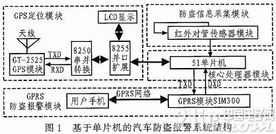
The car anti-theft alarm system has complex functions and adopts a modular design scheme, which is mainly composed of four parts, as shown in Figure 1. When the anti-theft information acquisition module collects the alarm signal, the GPS positioning module will start immediately and start receiving the positioning signal (latitude, longitude, altitude, etc.). At the same time, the core microprocessor connects the modules through various communication methods to control the coordination. Work, and carry out data analysis and processing, start the GPRS anti-theft alarm module to send the positioning data to the owner's mobile phone as a short message.
2 module design
2.1 Anti-theft information collection module
In this system, the infrared pair tube sensor circuit is used to collect anti-theft information, which is used to monitor whether someone illegally invades when the car is parked unattended. The sensor circuit is composed of an infrared transmitting and receiving pair tube, and can send an accurate monitoring signal to the microprocessor in time, which is simple to use, easy to observe, and high in sensitivity. The anti-theft information collection module is not the core function module of the system, and is only used to simulate whether the car is stolen or not during the system implementation process.
2.2 core processor module
The car burglar alarm system using GPS/GPRS technology has complex functions. In order to ensure the practicability and scalability of the system, it is necessary to select a high-performance core processor to coordinate the work of each module, in order to achieve a small system, high integration and reliability. Good performance and other performance, the design will use a cost-effective 8-bit 51 series microcontroller as the core processor.
2.3 GPS positioning module
1) Hardware part
As the best navigation and positioning system to date, GPS global positioning system is widely used in real life and is an important part of the development of information age. The GPS system consists of three parts: space satellite, ground support system and user equipment. The basic principles of positioning are referenced. The user only needs to design the user equipment part when using the GPS to implement the positioning function, that is, the GPS positioning module in FIG. 1 , which is used for receiving the GPS satellite transmission signal.
The car is positioned using the GT-2525 GPS chip. The GT-2525 GPS has 12 independent receiving channels using asynchronous serial communication. It can provide longitude, latitude, speed, altitude, world coordination time, frequency and GPS satellite orbit information. It has low voltage power supply, high sensitivity and high precision. High reliability, easy to use and so on. In addition, in order to improve the scalability of the system function, the core processor pin resources should be minimized in the system design. Therefore, the design of this module is: GT-2525 GPS receives the vehicle position information and uses the 8250 chip for serial Conversion, and through the 8255 parallel interface chip to achieve the connection with the microcontroller, the microcontroller analyzes and processes the data and displays it on the OCMJ2X8 (128X32) LCD. The LCD display is not a system function module, mainly used for GPS positioning module debugging. The structure of the GPS positioning module is shown in Figure 1.
2) Software part
The design process of the GPS positioning module software is shown in Figure 2. The detailed design of each part is as follows.
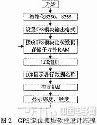
18250 chip initialization: Set the 8250 transmission line control register to implement the addressing divisor latch; set the divisor latch value according to the 8250 external clock frequency 1.843 2 MHz, baud rate 4800 BPS; set the transmission line control register to achieve the character data format: 8 bits Data bit, 2 stop bits, no parity.
28255 chip initialization : select the control word by writing mode, set the PA port as the output, realize the PA port to write the data to the LCD module: DB0~DB7, and set the PC port as the high 4-bit input and the low 4-bit output to realize the LCD module. Control of the BUSY port and REQ port.
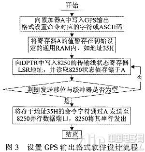
3 set the GPS output format:
The GT-2525 GPS uses the NMEA-0183 protocol, which has strict format requirements. The basic NMEA command directive is an ASCII string. Start with the '$' character to
4 receiving GPS module positioning data stored in off-chip RAM
After the MCU sends the output format setting command to the GPS module, the MCU will first receive the echo of the command, that is, the MCU first receives $PFST, NMEA, 2000.
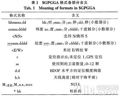
The NMEA standard message begins with "GP" followed by a 3-character message identification code. The message header and message content are separated by a comma, and the message ends with the check code (the check code consists of a '*' and two 16-bit check codes. The check code is calculated as follows: after the "$" character , before the "*" character, the result of the XOR of the first word and the second word, and then XOR with the third word, the result obtained after the loop).
The $GPGGA format for GPS output is $GPGGA, hhmmss.dd, xxmm.dddd,
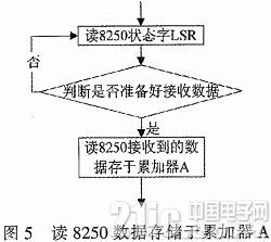
The receiving GPS data is stored in the off-chip RAM software design flow as shown in Figure 4, in which the software design of reading 8250 data stored in the accumulator A internal small module is shown in Figure 5. The design idea of ​​receiving the GPS module positioning data is: comparing the start character with "$" by using the comparison instruction, and starting the external RAM storage when the received start signal is "$", if the received start signal is not When "$", it will not be stored and continue to receive signals. When the received end signal is "0AH" (ie, a newline), the storage is ended. If the received end signal is not "0AH" (ie, a newline), the signal is continuously received.
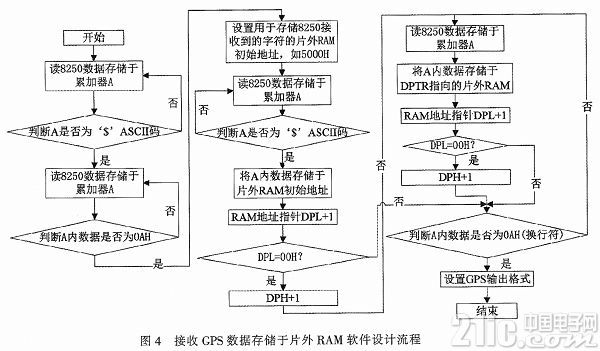
5 Extracting the longitude and latitude data from the off-chip RAM, which is displayed on the LCD screen and other functions belonging to the system and assisting in the debugging of the GPS positioning module, so it will not be described in this article.
2.4 GPRS anti-theft alarm module
1) Hardware design
The alarm methods currently used mainly include sound, light, electricity, and text. With the advent of the information age, it is an efficient and convenient way to realize real-time alarms by sending mobile phone short messages to remind users. Therefore, the system selects the GPRS module based on SIM300 communication chip as the system alarm module, which has the advantages of high speed and high reliability. The subscriber identity card (SIM card) of the called data service service is inserted into the GPRS module, and voice transmission and point-to-point data transmission can be realized through the SIM300 communication chip.
The GPRS module uses a standard serial port to communicate with the core processor. The connection circuit diagram is shown in Figure 6. Among them, the underlying design of the GPRS module can be referred to the literature.
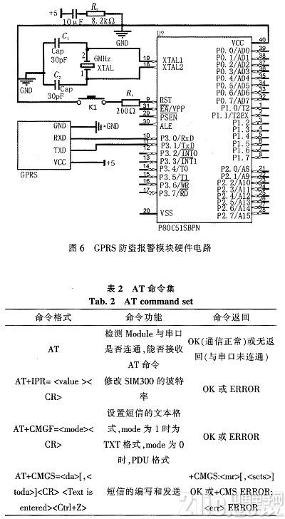
2) Software design
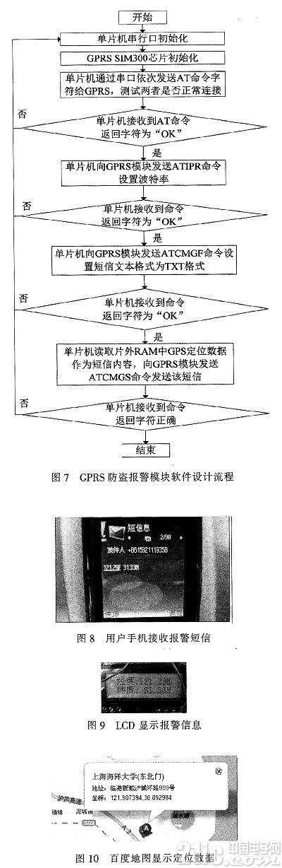
The single-chip microcomputer can control the SIM300 chip to write short messages through the AT command set, and send the designated mobile phone number through the GPRS network by using the SIM card. The short message content is GPS positioning data, which is read by the single chip from the off-chip RAM. The main AT commands in the system design are shown in Table 2. The programming flow chart of this module is shown in Figure 7.
3 system operation
According to the above scheme in the text, the car anti-theft alarm hardware circuit is designed, the program is written, and the software and hardware debugging is performed. The system is operated at Shanghai Ocean University (No. 999, Shanghai Hucheng Road). The debugging process is to place the hand in the middle of the infrared transmitting tube and the receiving tube to simulate the stolen scene of the car. After a very short time delay, the mobile phone successfully accepts. To locate the alarm information, as shown in Figure 9, at the same time, the GPS positioning module of the GPS positioning module also displays the vehicle positioning information, as shown in Figure 10. In addition, query Baidu map to get the longitude of the system running location, the latitude data is shown in Figure 11. The positioning error is within 0.6 degrees.
4 Conclusion
Comparing the results of the system operation with the results of Baidu map query, the car anti-theft alarm system designed in this paper has high accuracy and timeliness. In this paper, a simple infrared sensor circuit is used to simulate the car theft scenario. Therefore, further research work can be carried out around how to optimize the design of the theft information collection module, improve the design of the whole system, and improve its practicability.
Features
A Push Button Switch is a switch that has a knob that you push to open or close the contacts. In some pushbutton switches, you push the switch once to open the contacts and then push again to close the contacts. In other words, each time you push the switch, the contacts alternate between opened and closed. These types are commonly called latching switches. There are also Non latching push button switches that only maintain the switch contacts when the switch is help in position. Once the switch is let go, the current is broken and the switch turns off. Push switches are usually a simple on-off switch.
Push Switch,Push Button Switch,Micro Push Button Switch,Waterproof Push Button Switch
Ningbo Jialin Electronics Co.,Ltd , https://www.donghai-switch.com