
Today's touchscreen controllers use a variety of different methods to improve signal-to-noise ratio and filter out bad data from noise, including on-chip high-voltage transmit signals, specialized hardware acceleration, high-frequency emissions, adaptive frequency hopping techniques, and Saturated control technology. However, touch technology continues to evolve, covering aspects such as how touch controllers take advantage of these features, how to dynamically adapt to the noise present in the system, and how to accurately perform touch tracking under changing environmental conditions.
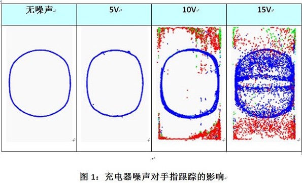
The effects of injected noise include large jitter (the touch coordinates reported for non-moving fingers vary greatly), no finger touches the screen but falsely report a finger touch, the finger touches the screen without reporting the presence of a finger, and even causes the device to be completely Locked and so on. If you take a touch screen phone as an example, this means that you can't unlock your phone (because you can't report finger manipulation), or you can dial the wrong number because of jitter or wrong touch. (I wanted to call a friend late at night, but the result was wrong. Boss, this question is not small). Figure 1 shows the results of using the best-selling smartphone on the market to test finger tracking (for example, draw a circle with one finger). As the noise increases, the position report of the finger on the panel (as shown in blue) will fail and an incorrect touch will be detected on the panel (shown in other colors).
How the touch screen controller responds to noise effects can have a significant impact on the quality experience of the user's touch interface. Poor touch performance under noisy conditions can cause customer dissatisfaction and increase the amount of returns. Due to the differences between the various noises, touch screen controllers need to be able to detect, distinguish, and cope with these noises, especially the two most common sources of noise: chargers and display noise.
Charger and common mode noise
A major problem with capacitive touch screen devices is that touch performance is degraded when the charger emits high-intensity high-frequency noise. Some mobile devices only provide limited touch function when plugging in the charger, or display information that the charger cannot be used when connecting a charger that is not suitable for the device, in order to cope with the problem of the high noise charger. The above solutions are not perfect at all. A quick look at the relevant information on the online forums and message boards, we can find that the problem of touch screen devices affected by the noise of the charger is very common, and it has already caused some consumers a headache.
USB is rapidly being promoted as a standard charging interface in mobile devices, which has also spawned a large number of low-cost aftermarket optional battery chargers. Many chargers focus more on cost issues than performance, and these chargers use inexpensive components or lack specific components that help reduce common mode noise.
The power supply and ground supply voltage of the device fluctuate relative to the ground pressure, but at the same time maintain the same differential pressure between the two, common mode noise is formed. This fluctuation affects the performance of the touch screen only when the grounded coupled finger touches the screen. The potential of the finger is the same as the ground pressure, and the power supply and grounding of the mobile phone fluctuate relative to it, causing noise to be injected into the touch screen through the finger. The amount of charge injected depends primarily on the peak-to-peak voltage of the noise.
In addition, the amount of charge transferred is also significantly affected by two other factors: the contact area between the finger and the touch screen, and the thickness of the touch screen covering the lens. The effects of these two factors can be understood by the capacitance equation of a parallel plate capacitor:
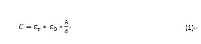
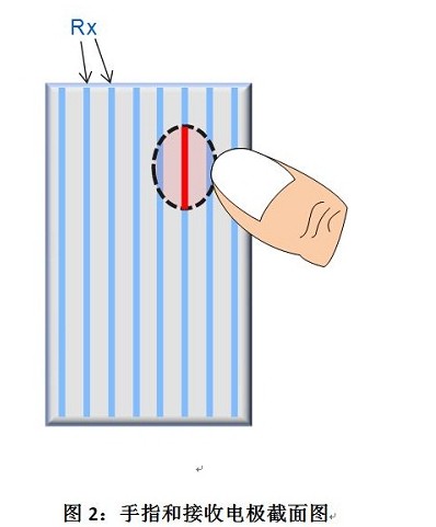
The higher the capacitance, the greater the noise injected into the touch screen. In this case, one side of the parallel plate of capacitance is formed by the finger contact area, and the other side is formed by the receiving electrode of the touch screen sensor. First, as the contact area between the finger and the touch screen increases, the capacitance increases proportionally. However, since the receiving electrode is composed of extremely narrow rows or columns, the actual functioning is the diameter of the finger (see Fig. 2).
Some OEMs use smaller fingers (such as 7 mm) to test their device's immunity to charger noise. However, this does not cover all use cases. A typical finger diameter is 9 mm and a typical thumb diameter is 18 to 22 mm. If you only test 7mm fingers, you can't make sure that the thumb unlocks the phone or manipulates the scrolling list. In fact, if we analyze the difference in diameter, then the 22 mm thumb is injected more than three times as much as the 7 mm finger!
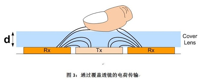
The distance (d) between the finger and the receiving electrode is mainly determined by the thickness of the touch screen covering lens (see Figure 3). Typical cover lens thicknesses range from 0.5 mm to 1.0 mm. This means that a device with a 0.5 mm cover lens has a "d" that is half the 1.0 mm coverage lens device and a capacitance of 2 times. In other words, the 0.5 mm cover lens implants twice as much noise as the 1.0 mm cover lens. As the appearance of the device moves toward a thinner and lighter trend, the thickness of the cover lens and the ability of the touch controller to withstand the lighter and thinner lenses cause greater noise.
Although the charger needs to pass several product certifications, there are no relevant requirements for common mode noise. In 2010, a group of mobile phone OEMs reached a consensus on the development of the general specification EN62684 to manage the maximum peak-to-peak voltage that the charger can tolerate in the frequency range. This specification requires that the noise generated by the charger not exceed 1Vpp (from 1kHz to 100kHz), while above 100kHz requires lower voltage strength. Typical optional market chargers do not follow this directive.
Although the noise generated by the lower noise charger is between 1–5Vpp, the noise range of the higher noise charger is 20–40Vpp, which results in a huge charge transfer. The amount of injected charge depends on the voltage amplitude of the noise (Q = C * V). Although the amount of noise is large, the touch screen controller must still be able to detect a finger that causes a small change in charge.
Capacitive touch-screen phones also face a new type of common-mode noise, the Mobile High-Definition Link (MHL), a standard interface for transmitting audio and video from mobile phones to HDTVs. The phone is connected to the HDTV via an MHL adapter, which converts the phone's USB interface into the TV's HDMI port. This common mode noise comes from the TV power supply and is passed to the phone via HDMI and USB cable.
Ceramic Line Post Insulator are a type of steel insulator, Line Post Insulator is used for supporting wires and resisting electric current, High Voltage Line Post Insulation consisting of one or more insulating members permanently glued to a metal base, sometimes with a cap,and can be double mounted on a metal base. The head bolt or one or several bolts are steel mounted on the support structure. Porcelain Power Line Insulators are suitable for temperatures between -40° C to +40° C, heights below 1000m(1000m and above can be amend base on GB311.1-1997), frequencies not exceeding 100Hz, voltages above 1000V, and mechanical loads within the rated values of the product.
| MAIN DIMENSIONS AND STANDARD PARTICULARS | |||||
| ANSI Class | 57-1 | 57-2 | 57-3 | 57-4 | 57-5 |
| Creepage Distance/mm | 356 | 559 | 737 | 1015 | 1145 |
| Dry Arcing Distance/mm | 165 | 241 | 311 | 368 | 438 |
| Cantilever Strength/kn | 12.5 | 12.5 | 12.5 | 12.5 | 12.5 |
| Low Frequency Dry Flashover Voltage/kv | 80 | 110 | 125 | 150 | 175 |
| Low Frequency Wet Flashover Voltage/kv | 60 | 85 | 100 | 125 | 150 |
| Critical Impulse Flashover Voltage, Pos/kv | 130 | 180 | 210 | 255 | 290 |
| Critical Impulse Flashover Voltage, Neg/kv | 155 | 205 | 260 | 340 | 380 |
| Test Voltage to Ground/kv | 15 | 22 | 30 | 44 | 44 |
| Maximum RIV at 1000KHZ/μv | 100 | 100 | 200 | 200 | 200 |
| Net Weight/kg | 5.2 | 9.0 | 11.0 | 16 | 23 |
| Dimensions of the pin/mm | M20(M16) | M20 | M20 | M20 | |


We warmly welcome friends both domestic and abroad to visit our company, if you have any questions, please contact with us directly.
Line Post Insulator
Line Post Insulator,Porcelain Power Line Insulators,Ceramic Line Post Insulator,High Voltage Line Post Insulation
FUZHOU SINGREE IMP.& EXP.CO.,LTD. , https://www.cninsulators.com