
How to use common instruments and electrician tools? Learn systematically and master the basic knowledge necessary for getting the most gas.
How to use common instruments I. How to use the multimeter
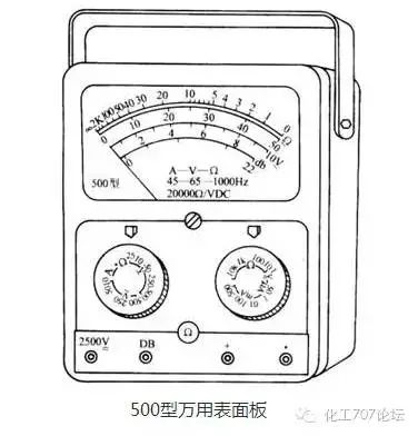
Multimeter can measure DC current, DC voltage, AC voltage and resistance, and some can also measure power, inductance and capacitance. It is one of the most commonly used instruments for electricians.

1, the basic structure and shape of the multimeter
The multimeter is mainly composed of three parts: indication part, measurement circuit and conversion device.
The indicating part is usually a magnetoelectric microammeter, commonly known as the meter head; the measuring part converts the measured electrical quantity into a small DC current suitable for the metering requirements, usually including a shunt circuit, a voltage divider circuit, and a rectifier circuit; measurement of different types of electricity And the choice of range is achieved through the conversion device.
2. How to use the multimeter
1 button (or jack) select to be correct
The red test lead cable should be connected to the red end button (or marked with a "+" jack). The black test lead should be connected to the black end button (or to the "-" jack) Some multimeters have a measuring terminal for AC and DC 2500V. When used, the black test stick is still connected to the black end button (or "-" jack), while the red test stick is connected to a 2500V terminal (or Inside the jack).

2 The position of the selector switch must be correct
According to the measuring object, switch the switch to the desired position. If the current is to be measured, the changeover switch should be turned to the corresponding current level and the measured voltage should be switched to the corresponding voltage level. Some universal surface boards have two switches, one to select the measurement type and the other to select the measurement range. When using, you should first select the measurement type and then select the measurement range.
3 range selection should be appropriate
According to the approximate range being measured, switch the switch to the appropriate range of this type. When measuring voltage or current, it is best to make the pointer in the range of one-half to two-thirds of the range, and the reading is more accurate.
4 correct reading
There are many scales on the scale of the multimeter, which are suitable for different objects to be measured. So while measuring, while reading on the corresponding scale, you should also pay attention to the cooperation of the scale reading and range file to avoid errors.
Correct use of 5 ohms
1) Select the appropriate magnification file
When measuring resistance, the override file should be selected so that the pointer stays in the dilute part of the scale line. The closer the pointer is to the middle of the scale, the more accurate the reading, the more to the left, the tighter the scale line, the more accurate the reading. difference.
2) Zero adjustment
Before measuring the resistance, the two test bars should be touched together, and the “zero adjustment knob†should be turned at the same time so that the pointer is just at the zero position of the ohm scale. This step is called zero adjustment of the ohm range. Each time you change the ohm range, repeat this step before measuring the resistance to ensure measurement accuracy. If the pointer cannot be adjusted to zero, the battery voltage is low and it needs to be replaced.
3) Can't measure resistance with electricity
When measuring the resistance, the multimeter is powered by a dry battery. The measured resistance must not be charged to avoid damage to the meter. When using an ohmic gap, do not short the two test bars to avoid wasting the battery.
6 Pay attention to operational safety
1) When using the multimeter, be careful not to touch the metal part of the test rod to ensure safety and accuracy of measurement.
2) When measuring higher voltage or larger current, it is not allowed to turn the switch with live, otherwise it may cause the switch to burn out.
3) After the multimeter is used up, it is best to switch the switch to the highest range of AC voltage. This file is the safest for the multimeter to prevent negligence and damage to the multimeter during the next measurement.
4) Before the test bar contacts the circuit under test, a full inspection should be performed to see if there is any error in the position of each part.
Second, the use of megohmmeter
Megohmmeter, commonly known as a rocker, is used to measure large resistance and insulation resistance. Its unit of measure is Megaohm (MΩ), so it is called megohmmeter. There are many types of megohmmeters, but their effects are roughly the same.

1, Megohmmeter selection
The voltage level specified for the megohmmeter should be higher than the insulation voltage level of the measured object. Therefore, 500V or 1000V megohmmeter can be used to measure the insulation resistance of equipment or circuit with a rated voltage below 500V.
When measuring the insulation resistance of a device or line with a rated voltage above 500V, a 1000~2500V megohmmeter should be used; when measuring the insulator, a 2500~5000V megohmmeter should be used.
In general, a megohmmeter with a range of 0 to 200 MΩ can be used to measure the insulation resistance of low-voltage electrical equipment.
2. Insulation resistance measurement method
The megohmmeter has three terminals. The two upper terminals are marked with “earth†(E) and “line†(L) respectively, and the lower one is marked with “protection ring†( Or "shielded") (G).

1 line to ground insulation resistance
The mezzanine "ground" terminal (ie, E terminal) is reliably grounded (generally connected to a grounding body), and the "line" terminal (ie, L terminal) is connected to the circuit under test, as follows Picture shows.
After the connection is made, the megohmmeter is shaken clockwise, the speed is gradually increased, and it is shaken at a constant speed of about 120 rpm. When the speed is stable and the pointer of the watch is stable, the value indicated by the pointer is the insulation resistance of the measured object. value.
In actual use, the two terminals E and L can also be connected arbitrarily. That is, E can be connected to the tested object, and L can be connected to the grounding body (ie, grounded). However, the G terminal can never be connected incorrectly.

2 Measure the insulation resistance of the motor
Connect the Megohmmeter E terminal to the case (that is, ground), and the L terminal to the winding of one phase of the motor. As shown in Figure b above, the measured insulation resistance value is the insulation resistance value of a phase to ground. .
3 Measure the insulation resistance of the cable
When measuring the insulation resistance between the cable's conductive core and the cable housing, the terminal E is connected to the cable housing, the terminal L is connected to the cable core, and the terminal G is connected to the insulating layer between the cable housing and the core. As shown in Figure c above.
3, use attention
1 Open and short circuit tests should be performed before use. Make L, E two terminals in the disconnected state, shake the megohmmeter, the pointer should point to "∞"; L and E two short posts, slowly rotate, the pointer should point at "0". Both of these meet the requirements, indicating that the Megohmmeter is good.
2 When measuring the insulation resistance of electrical equipment, it is necessary to cut off the power supply first, and then discharge the equipment to ensure personal safety and accurate measurement.
The 3 Megohmmeter should be placed in a horizontal position and hold the Megohmmeter firmly to prevent shaking during shaking. The shaking speed is 120 rpm.
4 Lead wires should use multiple strands of flexible wires, and have good insulation properties. The two leads should not be twisted together to avoid inaccurate measurement data.
5 Immediately after the measurement, discharge the object to be measured. Before the crank of the shaking table does not stop rotating and the object to be measured is not discharged, do not touch the measuring part of the object to be measured or remove the wire to prevent electric shock.
Third, the ammeter
The ammeter is connected in series with the circuit being measured and the current value is measured. According to the measured current properties can be divided into DC ammeter, AC ammeter and cross-current dual-use ammeter. There are micro-ammeters, milliammeters, and ammeters for the measurement range. According to the principle of action is divided into magnetic, electromagnetic and electric and so on.

Portable clamp ammeter
1, the choice of ammeter
When measuring direct current, it is more common to use magnetoelectric meters or electromagnetic or electric meters. When measuring alternating current, more electromagnetic instruments are used, and electric meters can also be used.
Magnetoelectric meters should be used in places with high requirements for measurement accuracy and high sensitivity. Electromagnetic meters with low prices and strong overload capacity are often used for occasions where measurement accuracy is not strict and measurements are large.
The range selection of the ammeter should be determined according to the measured current size, and the measured current value should be within the ammeter range. When it is not clear whether the measured current is large or small, use a large-scale ammeter to test it first to avoid damage to the instrument due to overload.
2, use methods and precautions
1 Always connect the ammeter to the circuit under test.
2 When measuring DC current, the polarities of “+†and “—†at the terminal of the ammeter cannot be connected wrongly, otherwise the instrument may be damaged. Magnetoelectric current meters are generally used only for measuring DC currents.
3 The appropriate range should be selected according to the measured current size. For an ammeter with two ranges, it has three terminals. When using it, it is necessary to read the terminal range mark and connect the common terminal and a range terminal in the circuit under test.
4 Select the appropriate accuracy to meet the needs of the measurement. The ammeter has internal resistance, and the smaller the internal resistance, the closer the measured result is to the actual value. In order to improve the accuracy of the measurement, an ammeter with a smaller internal resistance should be used as much as possible.
5 When measuring larger AC currents, the AC ammeter range is often enlarged by means of current transformers. The rated current of the current transformer secondary coil is generally designed to be 5 amps, and the AC current meter range used with it should also be 5 amps.
The indicated value of the ammeter is multiplied by the current transformer's current ratio and is the value of the actual current measured. The use of current transformer should make the transformer's secondary coil and core reliably grounded, the secondary coil must not be equipped with a fuse at one end, is strictly prohibited open circuit when used.

Fourth, the voltmeter
The voltmeter is connected in parallel with the circuit under test to measure the voltage of the circuit under test. According to the nature of the measured voltage is divided into DC voltmeter, AC voltmeter and AC voltage meter. There are millivolt and voltmeter points for the measurement range.
According to the principle of action is divided into magnetic, electromagnetic and electric and so on.

1, the choice of voltmeter
The principle and method of selecting the voltmeter is basically the same as the selection of the ammeter, which mainly considers the measurement object, the measurement range, the required accuracy, and the price of the instrument. The measurement accuracy requirements are not high, and electromagnetic voltage meters are generally used. For the high measurement accuracy and sensitivity requirements, often use magnetic-electric multi-range voltmeter, which is commonly used is the voltage range of the multimeter.
2, use methods and precautions
1 Make sure that the voltmeter is connected in parallel with the two ends of the circuit under test.
2 The voltmeter range should be greater than the voltage of the circuit under test to avoid damaging the voltmeter.
3 When using a magnetoelectric voltmeter to measure the DC voltage, pay attention to the “+†and “-†polarity marks on the terminals of the voltmeter.
4 The voltmeter has internal resistance. The greater the internal resistance, the closer to the actual value the measurement results are. In order to improve the accuracy of measurement, a voltmeter with a large internal resistance should be used as much as possible.
5 Use a voltage transformer when measuring high voltages. The primary coil of the voltage transformer is connected to the circuit under test. The secondary coil has a rated voltage of 100 volts and is connected to a voltmeter with a range of 100 volts.
The voltage meter indication value multiplied by the transformation ratio of the voltage transformer is the value of the actual voltage measured. The voltage transformer should be strictly prevented from short-circuiting in the operation of the secondary coil. Usually a fuse is set in the secondary coil as protection.
Fifth, grounding resistance measuring instrument
Grounding resistance refers to the grounded body resistance buried in the ground and the soil bulk resistance.


Instructions
1. Disconnect the connection point between the grounding trunk and the grounding body, or disconnect the connection points of all the grounding extensions on the grounding trunk. 2. Insert two ground rods into the ground 400mm deep, one from the grounding body 40m away, and the other from the grounding body 20m away.
3. Place the rocking watch in a flat place near the grounding body, and then perform wiring. 1 Connect the wire stub E and the grounding body E' of the grounding device with a connecting wire.
2 Connect the wire post C on the meter and the ground rod C′ 40m away from the grounding body with a connecting wire.
3 Connect the wire post P on the watch and the grounding rod P′ 20m away from the grounding body with a connecting wire. 4, according to the measured grounding body ground resistance requirements, adjust the coarse adjustment knob (there are three adjustable range). 5. Shake the shakes evenly at about 120 rpm. When the hands are deflected, the jog dial is adjusted until the hands are centered. The reading after setting with the fine-adjustment dial is multiplied by the coarse-adjustment positioning multiple, which is the grounding resistance of the measured grounding body. For example, if the fine tuning reading is 0.6, and the rough adjusted resistance positioning multiple is 10, then the measured grounding resistance is 6Ω. 6. In order to ensure the reliability of the measured grounding resistance, the bearing should be changed and retested. Take the average of several measured values ​​as the grounding resistance of the grounding body.

The electrician in the chemical industry is still an indispensable part. The commonly used electrical instruments and methods of use must be mastered as a qualified electrician.
Introduction to common tools for electricians 1. Test pencil
When using it, you must touch the metal part of the pen end with a finger, and make the small window of the pen tube backlight and toward yourself, so as to observe the brightness and darkness of the neon tube and prevent the misjudgment caused by too strong light. Its use method is shown in the figure below.
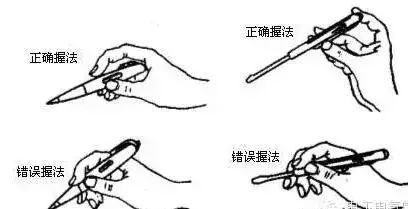
When the electric pen is used to test a charged body, an electric current flows through the charged body, the electric pen, the human body, and the ground. As long as the potential difference between the charged body and the earth exceeds 60V, the neon tube in the electric pen will emit light. Low-voltage electroscope detects the voltage range of 60~500V.
Precautions:
1. Before use, the electroscope must be tested at a power source to prove that the electroscope is really good before it can be used.
2. When inspecting the electricity, the electroscope should be brought close to the object to be measured until the neon tube is bright and it is not possible to directly contact the sample.
3. When inspecting the electricity, the finger must touch the metal body of the pen, otherwise the charged body will be misjudged as a non-charged body.
4. When inspecting electricity, prevent the finger from touching the metal part of the pen tip to avoid electric shock.
Second, the electric knife
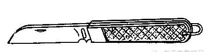
When using an electric knife:
1. Do not use for live work to avoid electric shock.
2. The knife edge should be cut outward and care should be taken not to hurt his fingers.
3. When cutting the insulation of the wire, make the blade face and the wire less acute, so as not to cut the wire.
4. After use, the blade will be folded into the handle

Three, screwdriver
When using a screwdriver,
1. When the screwdriver is large, except the thumb, forefinger and middle finger to grip the handle, the palm of the hand should also withstand the end of the handle to prevent slippage during rotation.
2. When the screwdriver is small, hold the handle with your thumb and middle finger, and use your index finger to press against the end of the handle.
3. When the screwdriver is long, press the handle with your right hand and turn it, while holding the middle part of the screwdriver with your left hand (not around the screw so as not to scratch your hand) to prevent the screwdriver from slipping.
Precautions:
1. When live working, do not touch the metal rod of the screwdriver to avoid electric shock.
2. As an electrician, you should not use a screwdriver with a metal lever on the top of the handle.
3. In order to prevent the metal rod from touching the human body or the adjacent charged body, the metal rod should be covered with an insulating tube.

Four, wire cutters
Wire cutters are widely used in electrical work. The jaws can be used to bend or clamp wire ends; toothed holes can be used to fasten or loosen nuts; knife edges can be used to cut wires or clamp wire insulation; side openings can be used to cut wire cores, wires, etc. harder Wire rods.
Precautions
1. Before use, make sure that the wire clamp insulation is good, so as to avoid electric shock accidents caused by electrified operation.
2. When cutting live wire, you must not use the knife edge to cut two wires of different potential at the same time (such as phase and neutral, phase and phase, etc.) to avoid short circuit accidents.

V. Long nose pliers
Needle-nose pliers, because of their sharp-edged head (as shown in the figure), are suitable for operation in tight working spaces.

Needle-nose pliers can be used to cut small wires; can be used to hold smaller screws, nuts, washers, wires, etc.; can also be used to shape single-strand wire (such as straight, curved, etc.). If you use a needle-nose pliers for live work, check that the insulation is good and do not touch the human body or adjacent live parts during operation.
4K Home Projector-watch ultra-high-definition movies without going out. Very suitable for home, office and school, compact design, powerful functions, this projector must be your best partner for entertainment or work.Thanks to the wireless connectivity, you'll be able to use it to download the videos, share files, enjoy more media activities.
4K Home Projector,Best 4K Projector,4K Projector,Full Hd Projector
Shenzhen Happybate Trading Co.,LTD , https://www.happybateprojectors.com